
Regenerative braking control device of electric vehicle

a technology of electric vehicles and control devices, which is applied in the direction of brake systems, braking components, transportation and packaging, etc., can solve the problems of disadvantageous deceleration of smooth electric vehicles and produced uncomfortable feelings, and achieve smooth stop and vehicle.

Active Publication Date: 2019-05-28
NISSAN MOTOR CO LTD
View PDF13 Cites 0 Cited by
  • Summary
  • Abstract
  • Description
  • Claims
  • Application Information

AI Technical Summary

Benefits of technology

This patent provides a control device for electric vehicles that can change the amount of regenerative braking according to the driver's intention. The device ensures a smooth deceleration and prevents vibrations during acceleration or stop of the vehicle. Additionally, the device takes into account the slope of the road surface to smoothly stop the vehicle on either an uphill or downhill gradient. Overall, this patent provides a simple solution for controlling regenerative braking in electric vehicles and improves the overall driving experience.

Problems solved by technology

However, as with a conventional electric vehicle regenerative braking control device, regenerative braking is performed at the same regeneration amount as in a high-speed area over a low-speed area, the vehicle is backed or vibrations (=acceleration vibrations) that shake the vehicle back and forth are produced by sudden removal of a torque, with the result that an uncomfortable feeling is produced.
Consequently, in the electric vehicle that can change the regeneration amount according to the intention of the driver, a passenger feels the vibrations to be shocks or feels them to be uncomfortable vibrations, and thus a feeling of smooth deceleration of the electric vehicle is disadvantageously degraded.

Method used


Image

  • Regenerative braking control device of electric vehicle
  • Regenerative braking control device of electric vehicle
  • Regenerative braking control device of electric vehicle

Examples


first embodiment

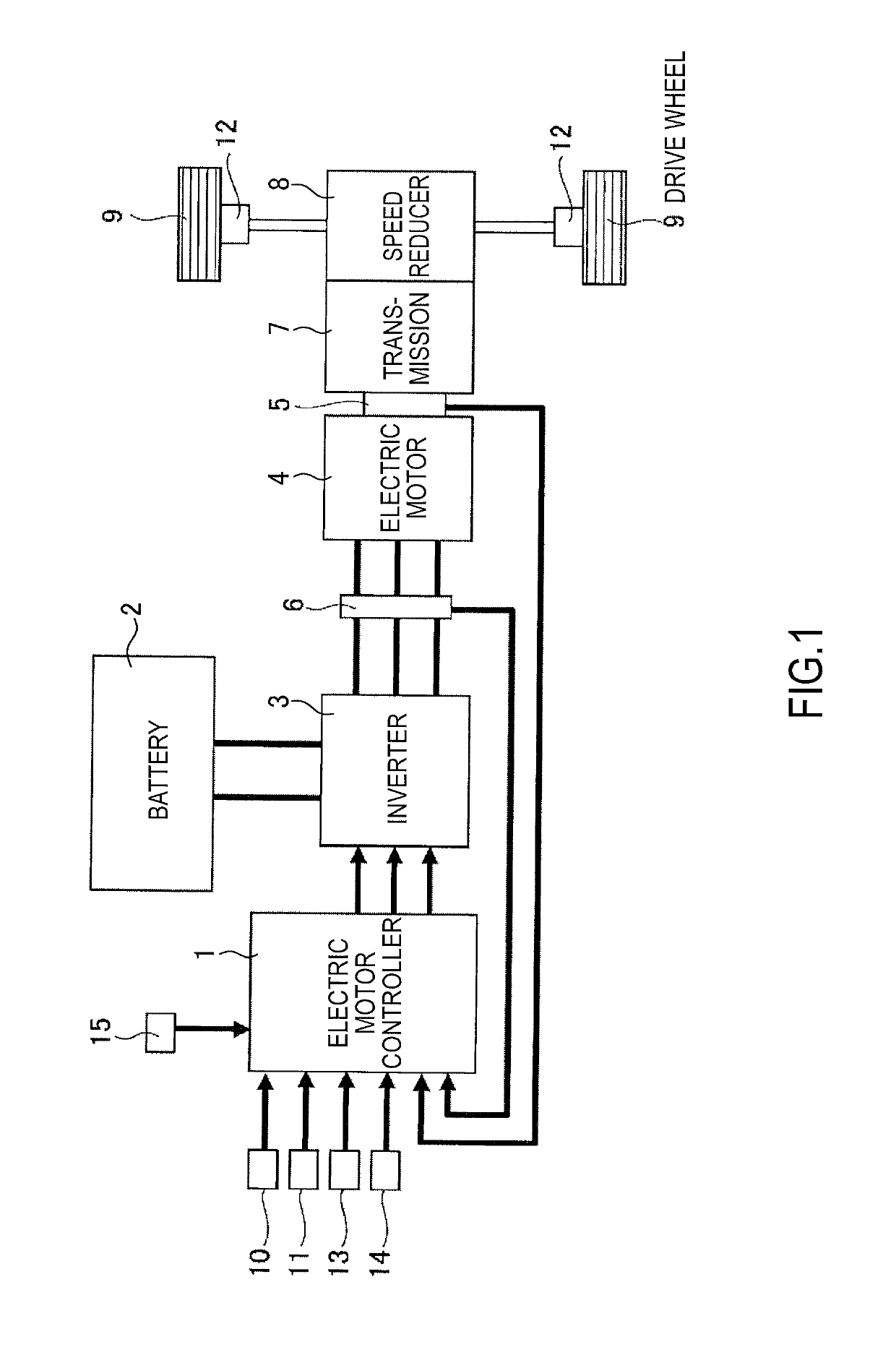
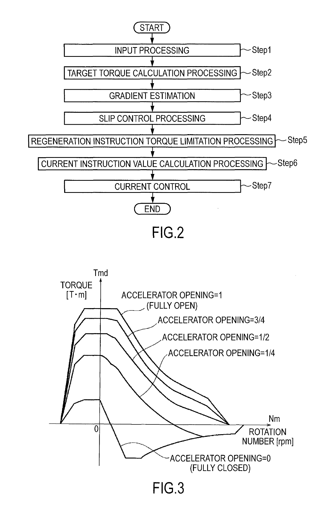
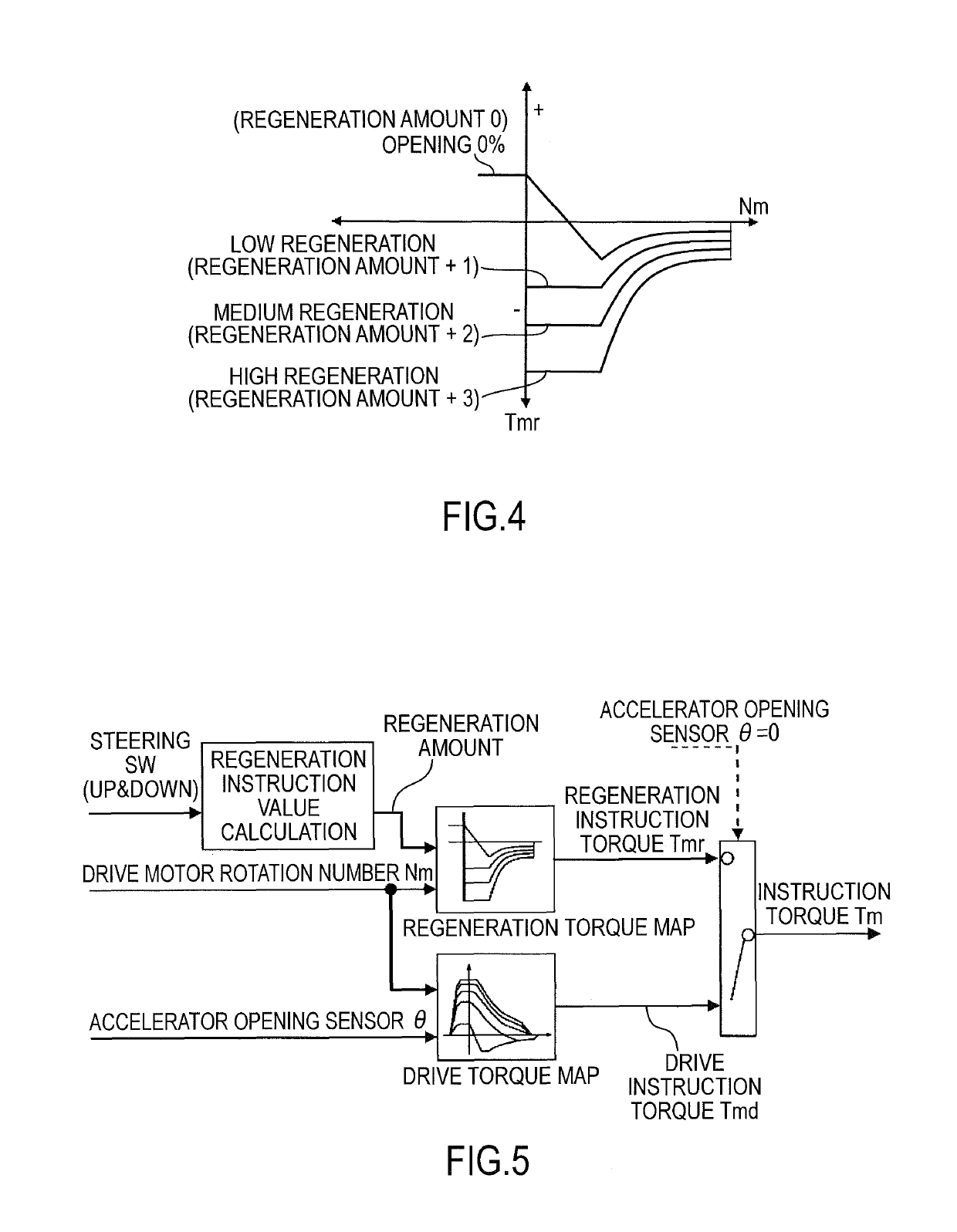
[0035]A configuration will first be described. The configuration of the regenerative braking control device of an electric vehicle (an example of the electric car) in the first embodiment are divided into an “overall system configuration”, a “regenerative braking control configuration” and a “regeneration instruction torque calculation configuration”, and they will be described.

[0036][Overall System Configuration]

[0037]FIG. 1 shows the electric vehicle to which the regenerative braking control device of the first embodiment is applied. The overall system configuration will be described below with reference to FIG. 1.

[0038]As shown in FIG. 1, the electric vehicle to which the regenerative braking control device of the first embodiment is applied includes an electric motor controller 1, a battery 2, an inverter 3, an electric motor 4, a motor rotation sensor 5, a current sensor 6, a transmission 7 and a speed reducer 8 and drive wheels 9.

[0039]The electric motor controller 1 inputs, a...


PUM


Abstract

A regenerative braking control device of an electric vehicle, wherein, in an electric vehicle system that includes an electric motor coupled to a drive wheel, the regenerative braking control device has an electric motor controller that controls powering or regeneration of the electric motor, and a regeneration amount setting unit that sets a regeneration amount by a driver operation and that can change the regeneration amount according to an intention of a driver. The electric motor controller includes a regeneration instruction torque limitation unit that limits, immediately before stop of the vehicle with a motor rotation speed in a low-speed area, the regeneration amount to be decreased as a motor rotation speed is lowered.

Description

TECHNICAL FIELD[0001]The present invention relates to a regenerative braking control device of an electric vehicle that can change a regeneration amount according to the intention of a driver.BACKGROUND ART[0002]Conventionally, with respect to a regenerative braking control device that is a control device using an electric motor of an electric vehicle as a drive source and that can obtain a braking force by the regenerative braking of the electric motor, a device is known that is intended to be able to adjust a regeneration amount according to the intention of a driver (JPH08079907A1).[0003]This conventional device includes a battery, a drive electric motor that can drive wheels by power from the battery and a drive system control unit that controls the operation of the electric motor. The conventional device also includes a mechanical braking unit that achieves a braking force according to the stepping force of a brake pedal input from the brake pedal and a regenerative braking uni...

Claims


Application Information

Patent Timeline
Patent Type & Authority Patents(United States)
IPC IPC(8): B60L7/18B60L7/26B60L7/14B60T1/10B60L15/20
CPCB60L7/18B60L7/14B60L7/26B60L15/2009B60L15/2018B60T1/10Y02T10/7275B60L2240/421B60L2240/423B60L2240/461B60L2240/465B60T2270/604Y02T10/645B60L2240/14Y02T10/64Y02T10/72
Inventor SAWADA, AKIRA
Owner NISSAN MOTOR CO LTD
Learn More