Method for heating water in a machine for making and dispensing drinks

a technology for drinking machines and heating water, which is applied in the field of heating water in a drinking machine for making and dispensing beverages, can solve the problems of complex and expensive operation of large energy consumption for maintaining water at high temperatures, and the need for accurate maintenance of heating ducts, so as to simplify the replacement of heating ducts and optimize space. , the effect of reducing the cost of replacemen

Active Publication Date: 2018-09-06
RHEAVENDORS SERVI CES SPA
View PDF4 Cites 4 Cited by
  • Summary
  • Abstract
  • Description
  • Claims
  • Application Information

AI Technical Summary

Benefits of technology

[0014]The present invention provides a method and device for heating water in a machine for making and dispensing beverages, that avoids the drawbacks of the known art.
[0015]According to one aspect, the present invention provides a method for feeding and heating water in an assembly that includes a device for heating water, in a machine for making and dispensing beverages. The method and device provide for heating and feeding water at a determined temperature that can be selected by the user, and with a determined flow rate based on the type of beverage to be dispensed. The disclosed device and method provide for heating the water rapidly in a machine for making and dispensing beverages. The device is inexpensive, simple to use, benefits from reduced power consumption and replacing the device is simple, quick and cheap.
[0018]An advantageous aspect of the present invention is that in case of malfunctions, such as for example a reduced efficiency or a blocking of the heating duct due to limescale deposit, it is possible to replace only the duct simply and rapidly, i.e. there is no need to replace the whole heater as it is designed so that the winding of electromagnetic induction and the metal duct are two physically-separated pieces. This provides for simplified maintenance of the electric part (winding of electromagnetic induction) and the hydraulic part (heating duct), because they may be separately maintained.
[0021]To optimize space, the duct may advantageously have a spiral shape, and the inlet and the outlet of the duct may be on the same end so that the replacement of the heating element is made easy. To further simplify the replacement of the heating duct, push-in fittings are present which allow connecting and disconnecting the heating duct from the rest of the hydraulic circuit without interfering with the winding of electromagnetic induction.

Problems solved by technology

It is then necessary to maintain the water contained in the heating device at a desired temperature, also when the machine is not operating, so that to assure a dispensing of the beverage at the desired temperature without long waiting times. Then, if the machine is not operative for a long time, there will be a great energy consumption for maintaining the water at high temperatures (usually higher than 85° C.).
The main problems related to water heating, in machines for making and dispensing beverages, are due to thermal inertia with which a determined water mass is heated; in order to have a quick water heating the phenomenon of electromagnetic induction can be used for generating eddy currents inside an electrically conductive element in contact with the water to be heated; the eddy currents dissipate energy, because of Joule effect, in form of warmth heating the conductive element and consequently the water contacting therewith.
Anyway, the afore said heaters have a problem: inside the heating pipe the limescale contained in the water will deposit because of heating; then, inside the heating pipe, an inner coating of limescale will form that, at the beginning, limits the heat conduction from the pipe towards the water and, successively, will be able to block the inside of the heating pipe with the relative damage of the device or the whole machine.
Then, the above-mentioned heaters have the problem of needing an accurate maintenance of the heating duct.
In case in which the heating duct is blocked, the replacement of these heaters is a complex and expensive operation.

Method used


Image

  • Method for heating water in a machine for making and dispensing drinks
  • Method for heating water in a machine for making and dispensing drinks
  • Method for heating water in a machine for making and dispensing drinks

Examples


Embodiment Construction

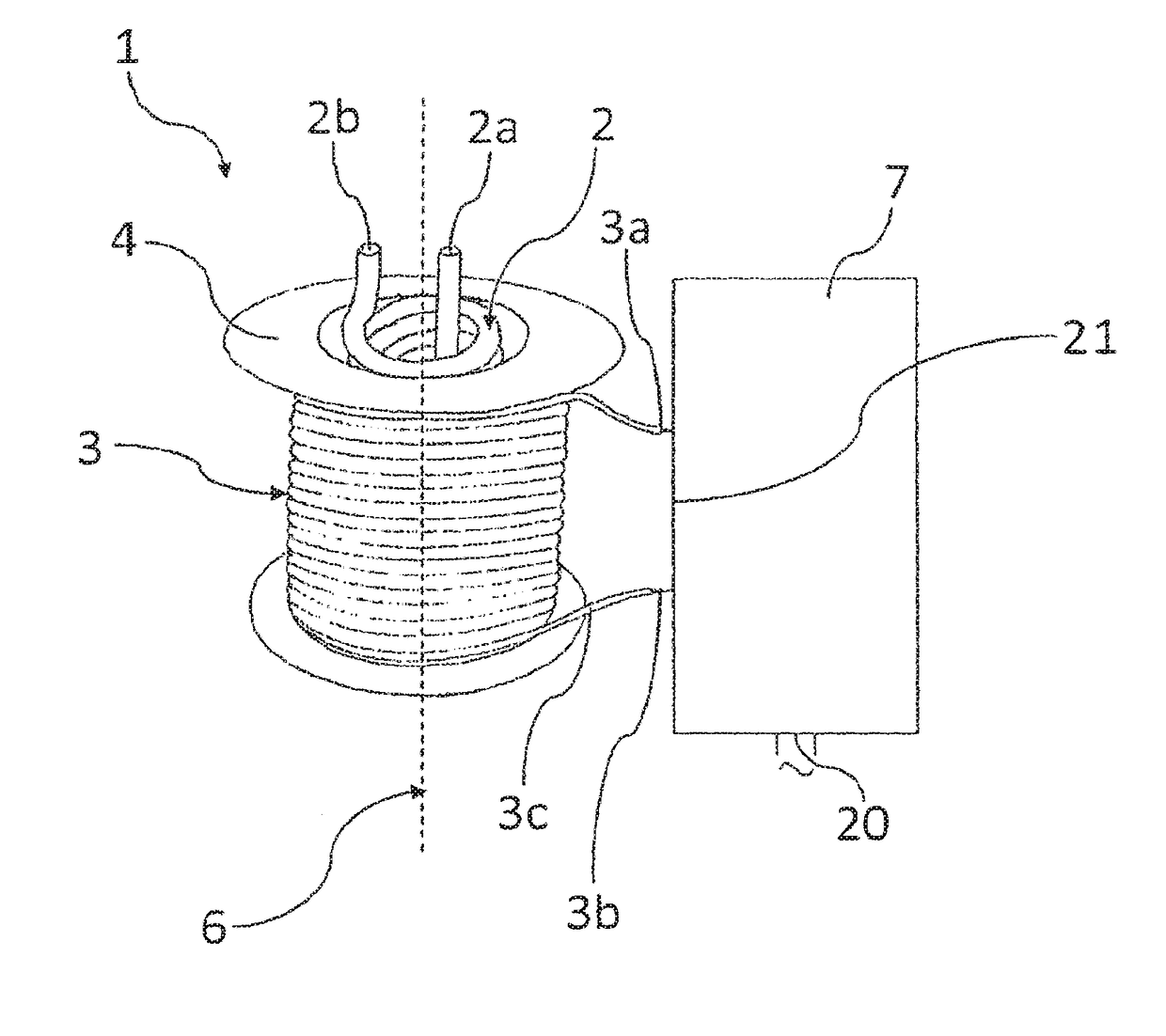
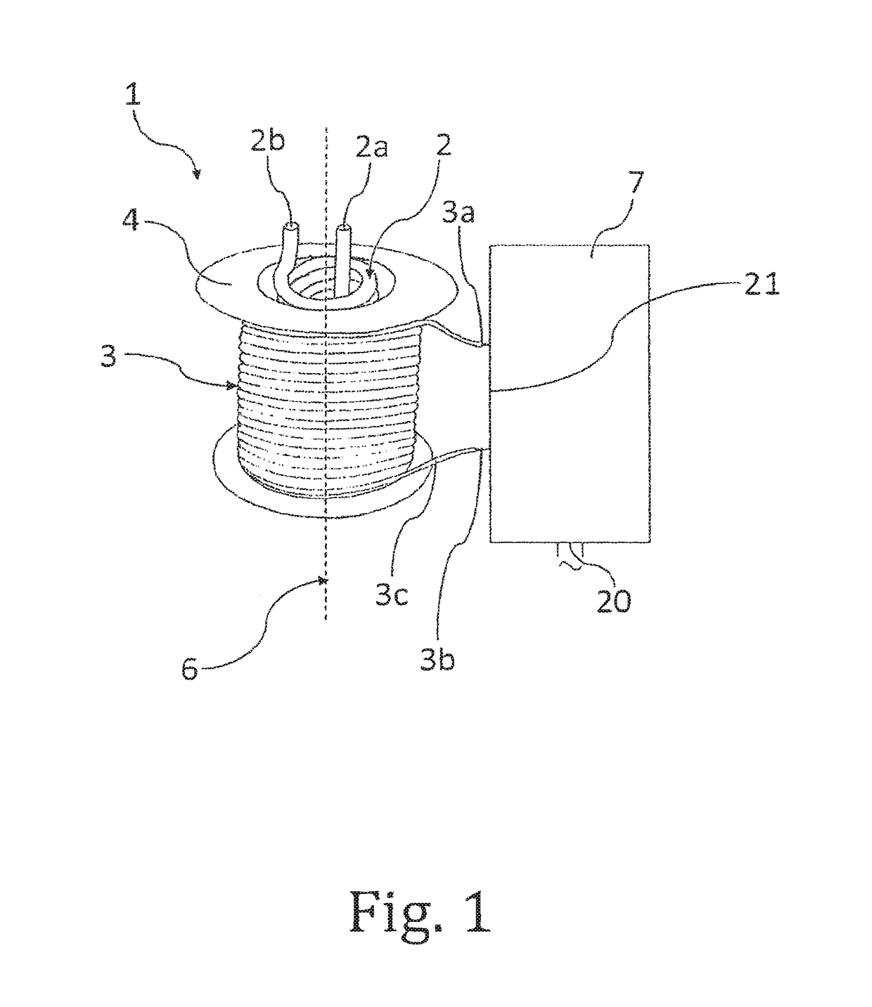
[0031]Referring to FIGS. 1 and 2, the device 1 for heating water in a machine for making and dispensing beverages comprises a metal duct 2 for the water flow between an inlet 2a and an outlet 2b and a winding of electromagnetic induction 3 whose loops are wound around a spool 4, made of an electrically insulating material. The spool 4 has a cavity 5 with a substantially cylindrical shape, with a symmetry axis 6 coincident with that of the winding 3. In the particular shown embodiment, the metal duct 2 is made of electrically conductive material, preferably of ferromagnetic material and has the shape of a cylindrical spiral.

[0032]The metal duct 2 is housed inside the cavity 5, so that the spool 4 and the metal duct 2 are separated at least in part by a gap, therefore in such a way that they are physically separated, so in such a way that the duct 2 could loosely slide inside the cavity 5.

[0033]With the term “gap” is meant a space region in which, substantially, there are no mechanica...


PUM


Abstract

A method for heating water in a machine for making and dispensing beverages, the machine having a device with at least one heating metallic duct and a winding of electromagnetic induction. The device is part of a heating and feeding assembly wherein, by a logical unit, a method is carried out which, for every beverage type the machine can dispense, the temperature of heated water is brought to a specific temperature value that can be selected by the user.

Description

RELATED APPLICATIONS[0001]This application is a divisional application of pending U.S. application Ser. No. 15 / 032,641 filed 28 Apr. 2016, which is a US national phase application of international application No. PCT / IB2014 / 002243, filed 28 Oct. 2014, which designates the US and claims priority to European Application No. EP 13005127.9 filed 29 Oct. 2013, the contents of each of which are hereby incorporated by reference as if set forth in their entireties.TECHNICAL FIELD[0002]The present invention concerns a method for heating water in a machine for making and dispensing beverages such as, for example, coffee, tea, and chocolate. The present invention further concerns a machine that includes a feeding and heating assembly adapted to carry out such a method.BACKGROUND OF THE INVENTION[0003]Machines for making and dispensing hot beverages provided with devices for heating water are known, generally defined as boilers or kettles; such devices, usually supplied by electric current, are...

Claims


Application Information

Patent Timeline
Patent Type & Authority Applications(United States)
IPC IPC(8): A47J31/54G05D23/19F24H1/12F24H9/20H05B6/10A47J31/60F24H9/18
CPCG05D23/1931F24H2250/08F24H1/121F24H9/2028A47J31/542H05B2206/022H05B6/108A47J31/60F24H9/1818A47J31/465A47J31/56A47J31/00F24H15/174F24H15/215F24H15/20F24H15/32F24H15/37F24H15/219F24H15/34F24H15/238
Inventor DOGLIONI MAJER, CARLO
Owner RHEAVENDORS SERVI CES SPA
Why Eureka
Try Eureka