Hemostatic device

a technology of hemostatic device and radial artery, which is applied in the field of hemostatic device, can solve the problems of vessel occludement, decreased excessive blood flow rate of ulnar artery, etc., and achieves the reduction of numbness or pain, reducing the blood flow rate of radial artery, and enhancing hemostatic effect.

Inactive Publication Date: 2018-09-06
TERUMO KK
View PDF0 Cites 7 Cited by
  • Summary
  • Abstract
  • Description
  • Claims
  • Application Information

AI Technical Summary

Benefits of technology

[0005]In response to such a problem, for example, when a pressing member for pressing the ulnar artery is further provided in the above-described hemostatic device, it is considered that an excessive increase in blood flow flowing to the ulnar artery may be prevented by pressing the ulnar artery, thereby suppressing a decrease in blood flow rate of the radial artery at the time of pressing the radial artery.
[0007]The hemostatic device disclosed here is configured to enhance the hemostatic effect by suppressing a decrease in blood flow rate of a radial artery, and reducing numbness or pain caused by pressing an ulnar artery.
[0009]According to the hemostatic device configured as described above, it is possible to enhance hemostatic effect by suppressing a decrease in blood flow rate of a radial artery. In addition, the length of the pressing member along the longitudinal direction of the band is shorter than the width of the pressing member along the direction orthogonal to the longitudinal direction of the band. For this reason, a part in which the pressing member comes into contact with the arm at the time of mounting the hemostatic device on the arm has a shape extending along running of the ulnar artery. In this way, it is possible to narrow a range of a part other than the ulnar artery (a tendon, a nerve, etc.) pressed by the pressing member while favorably pressing the ulnar artery by the pressing member. As a result, it is possible to reduce numbness or pain caused by pressing the ulnar artery.

Problems solved by technology

For this reason, when only the radial artery is pressed (compressed) for a long time, blood may hardly flow to the radial artery, and a blood flow rate of the ulnar artery may excessively increase.
As a result, a blood flow rate of the radial artery decreases, so that the blood vessel occludes or the amount of platelets, etc. decreases, thereby requiring a long time for hemostasis at the puncture site.
However, in the hemostatic device configured as described above, when the pressing member presses a wide range along a circumferential direction of the arm, a tendon, a nerve, etc. around the ulnar artery are also pressed, which causes numbness or pain.

Method used


Image

  • Hemostatic device
  • Hemostatic device
  • Hemostatic device

Examples


first embodiment

Modification of First Embodiment

[0093]First, a description will be given of second inflatable portions 160, 260, 360, and 460 according to Modifications 1 to 4. In the description below, features that are the same or similar to those described above are identified by the same reference numerals and a detailed description of such features is not repeated.

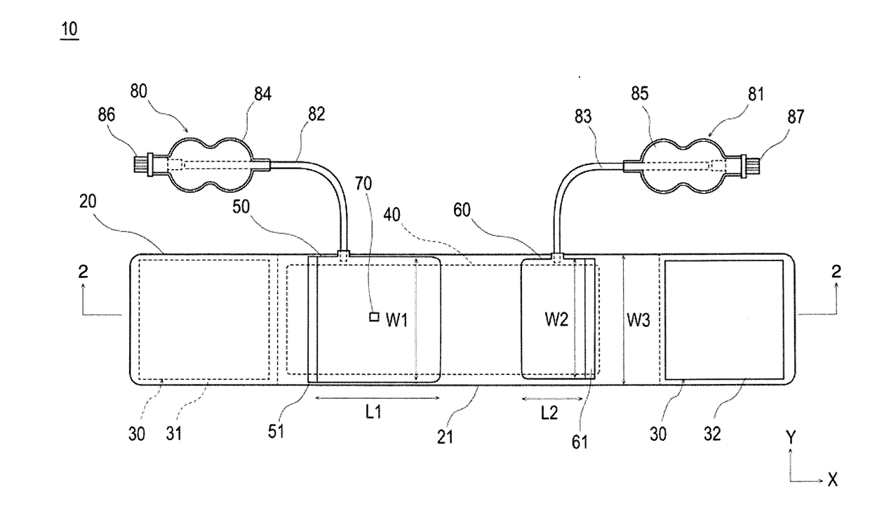
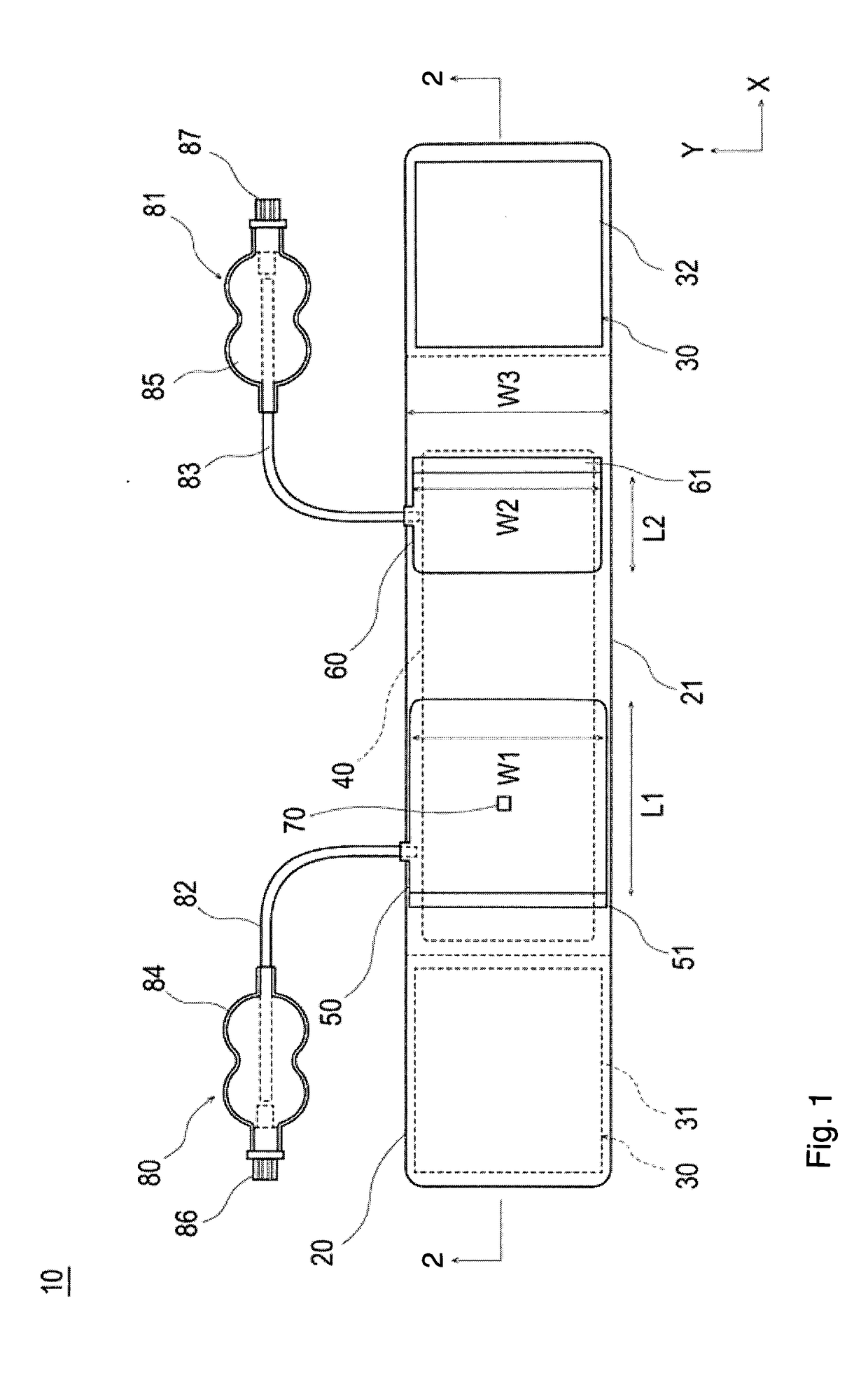
[0094]While an external shape of the second inflatable portion 60 according to the above-described embodiment is a rectangle in a state of not being inflated (see FIG. 1), the external shape of the second inflatable portion 160 according to Modification 1 is a trapezoidal shape (see FIG. 7(A)). The second inflatable portion 160 may be connected to the band 20 through a second holding portion 161. In addition, a maximum length L21 of the second inflatable portion 160 along the longitudinal direction of the band 20 (a maximum separation distance between two sides of the trapezoidal extending along a Y direction) may be shorter than a m...

second embodiment

Modification of Second Embodiment

[0177]In the hemostatic device 10 according to the second embodiment, a member (inflatable portion) that presses the puncture site 220 includes the single first inflatable portion 50 that inflates by injection of a fluid. Meanwhile, as illustrated in FIG. 16, a hemostatic device 100 according to a modification of the second embodiment has a feature in that a fluid is injected in common with the second embodiment. However, the hemostatic device 100 is different from the second embodiment in that a member (inflatable portion 150) that presses the puncture site 220 includes two members corresponding to a main compression portion 151 and an auxiliary compressing portion 152.

[0178]In addition, in the hemostatic device 10 according to a second embodiment, the member (pressing portion) that presses the ulnar artery 230 includes the single second inflatable portion 60 that can inflate by injection of a fluid. On the other hand, in the hemostatic device 100 a...

third embodiment

Modification 2 of Third Embodiment

[0262]In a hemostatic device 12 according to Modification 2 of the third embodiment, as illustrated in FIG. 24, FIG. 25(A), and FIG. 25(B), a main body 261 and a projection 262 included in a pressing member 260 are configured as separate members. The other aspects and configurations are substantially the same as that of the above-described third embodiment. In the description below, features that are the same or similar to those described above are identified by the same reference numerals and a detailed description of such features is not repeated.

[0263]As illustrated in FIG. 25(A), the main body 261 may be made of a flexible material, and presses the projection 262 by inflating in response to injection of a fluid.

[0264]The projection 262 may be made of a harder material than the material forming the main body 261, and presses the ulnar artery 230 by receiving a pressing force from the main body 261. In the present embodiment, as illustrated in FIG...


PUM


Abstract

A hemostatic device includes a flexible band allowed to be wrapped around a wrist in which a radial artery and an ulnar artery run, a hook and loop fastener that secures the band in a state of being wrapped around the wrist, an inflatable portion connected to the band and allowed to press a puncture site of the radial artery by being inflated in response to injection of a fluid, and a pressing member disposed at a different position from a position of the inflatable portion in a longitudinal direction of the band and allowed to press the ulnar artery. Further, a length of the pressing member along the longitudinal direction of the band is shorter than a width of the pressing member along a direction orthogonal to the longitudinal direction of the band.

Description

CROSS-REFERENCES TO RELATED APPLICATIONS[0001]This application is a continuation of International Application No. PCT / JP2016 / 075912 filed on Sep. 2, 2016, which claims priority to Japanese Application No. 2015-174197 filed on Sep. 3, 2015, Japanese Application No. 2015-174198 filed on Sep. 3, 2015 and Japanese Application No. 2015-174201 filed on Sep. 3, 2015, the entire content of all four of which is incorporated herein by reference.TECHNICAL FIELD[0002]The present invention generally relates to a hemostatic device for performing hemostasis by pressing a punctured site.BACKGROUND ART[0003]Recently, treatment / examination, etc. have been percutaneously performed by puncturing a blood vessel such as a radial artery, etc. of an arm, introducing an introducer sheath to a puncture site, and inserting a catheter, etc. into a lesion of the blood vessel, etc. through a lumen of the introducer sheath. When such a procedure is performed, it is necessary to perform hemostasis at the puncture ...

Claims


Application Information

Patent Timeline
Patent Type & Authority Applications(United States)
IPC IPC(8): A61B17/135
CPCA61B17/135A61B2017/00557A61B17/1325
Inventor MATSUSHITA, SHUHEIYAGI, HIROSHI
Owner TERUMO KK
Why Eureka
Try Eureka