Eureka AIR delivers breakthrough ideas for toughest innovation challenges, trusted by R&D personnel around the world.

Optical print head and image forming device

Active Publication Date: 2018-09-06
KONICA MINOLTA INC
View PDF0 Cites 0 Cited by
  • Summary
  • Abstract
  • Description
  • Claims
  • Application Information

AI Technical Summary

Benefits of technology

The present patent aims to provide an optical print head and image forming device that can prevent displacement of OLEDs and minimize the transfer of heat from a driver IC to a lens holder.

Problems solved by technology

Temperature increase of the driver IC 800 occurring in accordance with optical writing operations may cause malfunction or the like.
Such thermal expansion causes changes in positions of the components relative to each other and a reduction in condensing ratio of light emitted from the OLEDs 712 and condensed onto the outer circumferential surface of the photoreceptor drum 750, and consequently causes image quality deterioration.

Method used


Image

  • Optical print head and image forming device
  • Optical print head and image forming device
  • Optical print head and image forming device

Examples


Embodiment Construction

[0027]Hereinafter, one or more embodiments of the present invention will be described with reference to the drawings. However, the scope of the invention is not limited to the disclosed embodiments.

[0028]The following describes an embodiment of an optical print head and an image forming device pertaining to the present disclosure, with reference to the drawings.

[1] Structure of Image Forming Device

[0029]The following describes a structure of an image forming device pertaining to the present embodiment.

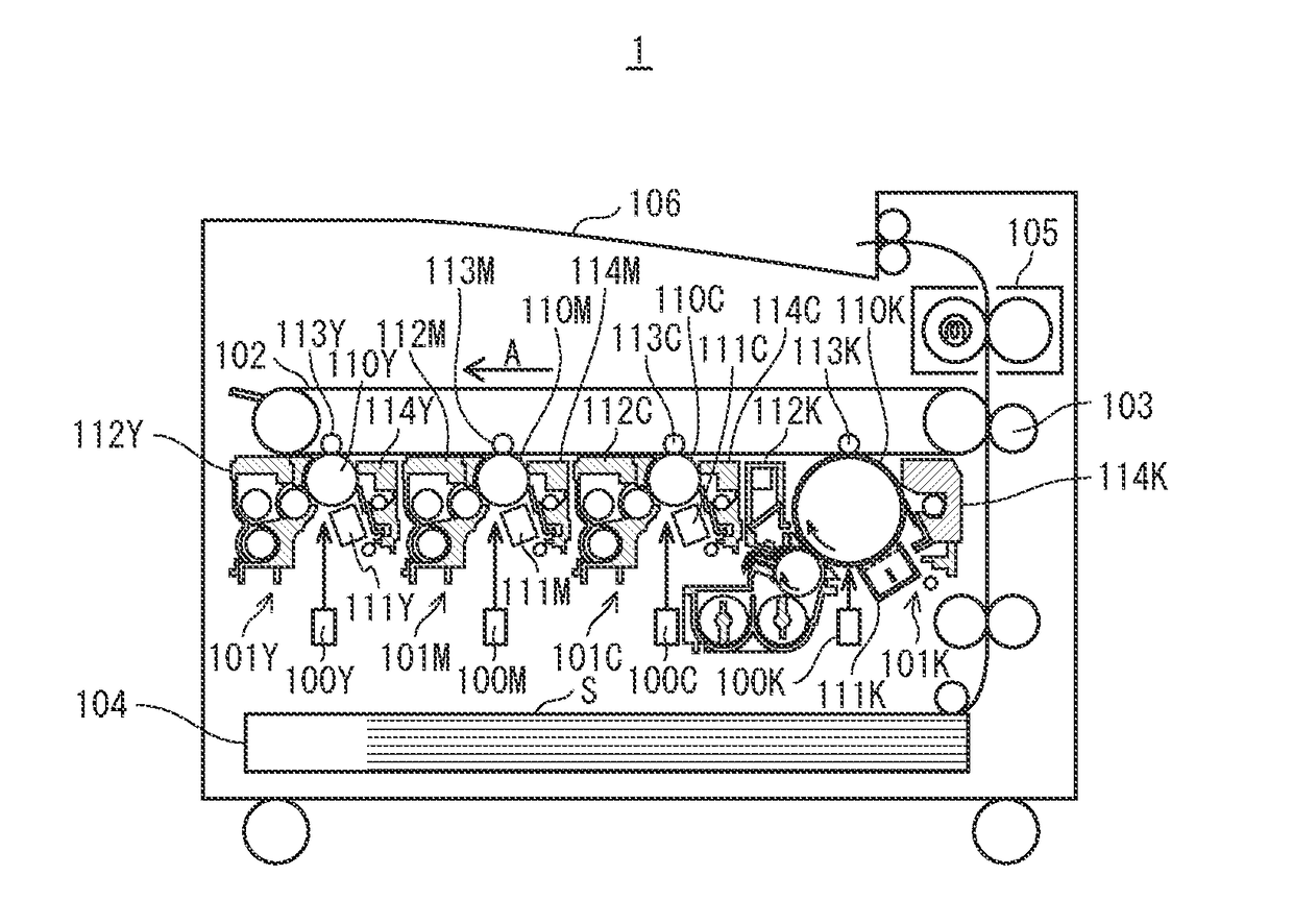
[0030]In FIG. 1, an image forming device 1 is a so-called tandem-type color printer device, and includes image forming units 101Y, 101M, 101C, and 101K forming images of colors yellow (Y), magenta (M), cyan (C), and black (K), respectively. The image forming unit 101Y includes an optical print head 100Y, a photoreceptor drum 110Y, an electricity charging device 111Y, a developing device 112Y, and a cleaning device 114Y. Similarly, the image forming unit 101M includes an optical print h...


PUM


Abstract

An optical print head, including: an elongated substrate having a line-shaped region in which light-emitting elements are arranged; an optical member condensing light from the light-emitting elements onto an irradiation target; a holding member holding the optical member; a base member holding the substrate and the holding member; an integrated circuit mounted in a first region in proximity of an end in a longitudinal direction of the substrate on a first surface of the substrate facing the base member, heat being generated in the integrated circuit during optical writing; and a thermally conductive member between the integrated circuit and the base member. In the optical print head, the holding member has a support portion contacting the substrate in a second region at a position differing from the first region in plan view on a second surface of the substrate not facing the base member.

Description

[0001]This application claims priority to Japanese Patent Application No. 2017-038184 filed Mar. 1, 2017, the contents of which are hereby incorporated herein by reference in their entirety.BACKGROUNDTechnical Field[0002]The present disclosure relates to optical print heads (also referred to as optical writing devices) and image forming devices, in particular to a technology for helping prevent image quality deterioration caused by heat from a semiconductor component that controls light amount emitted from the optical print head.Description of the Related Art[0003]Recently, in the technical field of electrophotographic image forming devices, optical print heads using organic light-emitting diodes (OLEDs) for light-emitting elements are developed in order to achieve downsizing and cost reduction.[0004]As illustrated in FIG. 7 and FIG. 8, an optical print head 700 that uses OLEDs forms an electrostatic latent image through condensing light emitted from the OLEDs 712 onto an outer circ...

Claims


Application Information

Patent Timeline
IPC IPC(8): B41J2/45G02B7/02H04N1/03H04N1/028
CPCB41J2/451G02B7/02H04N1/0306H04N1/02815G03G15/04054B41J2/447B41J2/45G03G15/04045H10K71/13
Inventor YUASA, TAKAFUMITANIYAMA, AKIRATACHIBE, HIDENARI
Owner KONICA MINOLTA INC
Why Eureka
Eureka Blog
Learn More