Eureka AIR delivers breakthrough ideas for toughest innovation challenges, trusted by R&D personnel around the world.

Electronic circuit module

Inactive Publication Date: 2009-04-09
ALPS ALPINE CO LTD
View PDF5 Cites 1 Cited by
  • Summary
  • Abstract
  • Description
  • Claims
  • Application Information

AI Technical Summary

Benefits of technology

[0010]The present invention provides an electronic circuit module in which the attachment position of a cover body can be set highly accurately with respect to a circuit substrate.
[0012]Accordingly, by disposing the claw segments of the cover body respectively within the cutout portions in the two opposite side surfaces of the circuit substrate, the cover body can be attached to the circuit substrate without play in both the thickness and width directions of the claw segments. Consequently, displacement of the cover body can be effectively suppressed in the in-plane direction of the circuit substrate.
[0013]In the above-described electronic circuit module, the cutout portions and the notches are preferably formed with a same drill. In this manner, the cutout portions having the notches can be formed with high accuracy, whereby the attachment position of the cover body can be set highly accurately with respect to the circuit substrate.
[0014]Furthermore, in the above-described electronic circuit module, it is preferable that an undersurface of the circuit substrate have arranged thereon a plurality of solder balls, and that the notches extend inward between outermost-arranged solder balls of the plurality of solder balls. In this manner, the tip end of each notch can be positioned as close as possible to the outermost solder balls, whereby an electronic circuit module of a flip-chip mounting type can be readily reduced in size.

Problems solved by technology

Although the claw segments 3a of the cover body 3 can be easily positioned in the thickness direction thereof within these cutout portions 2, the cutout portions 2 with this shape are problematic in that the claw segments 3a cannot be positioned accurately in the width direction thereof.
Although this configuration can allow the cover body 3 to be set in place highly accurately with respect to the circuit substrate 1 in both the X and Y directions, the cutout portions 2 increased to four sections in this manner can lead to many dead spaces created on the circuit substrate 1, thus unfavorably reducing the route flexibility for the wiring pattern and also making the cover body 3 into a complex shape.

Method used


Image

  • Electronic circuit module
  • Electronic circuit module
  • Electronic circuit module

Examples


Embodiment Construction

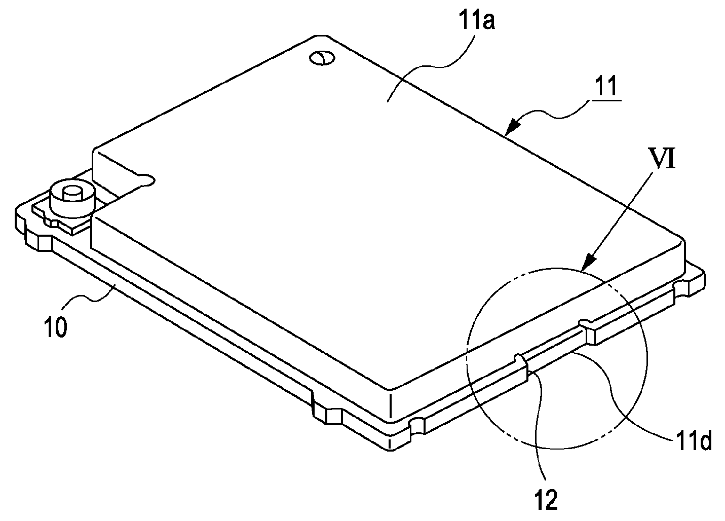
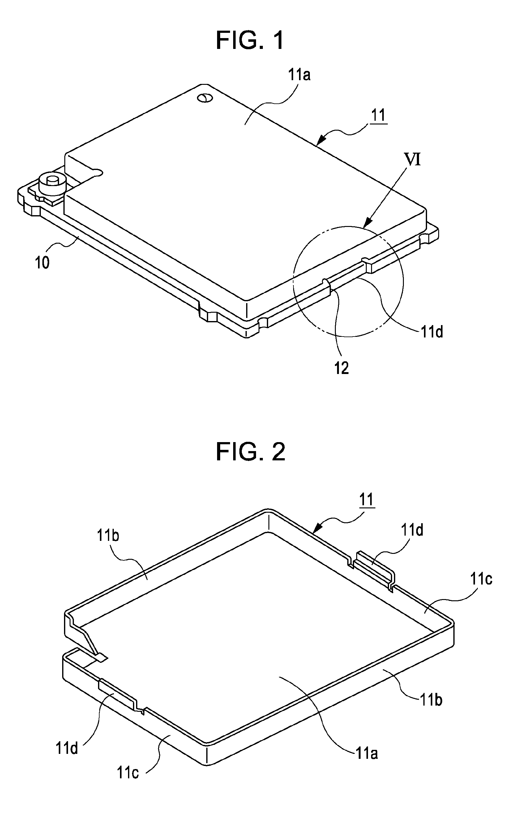
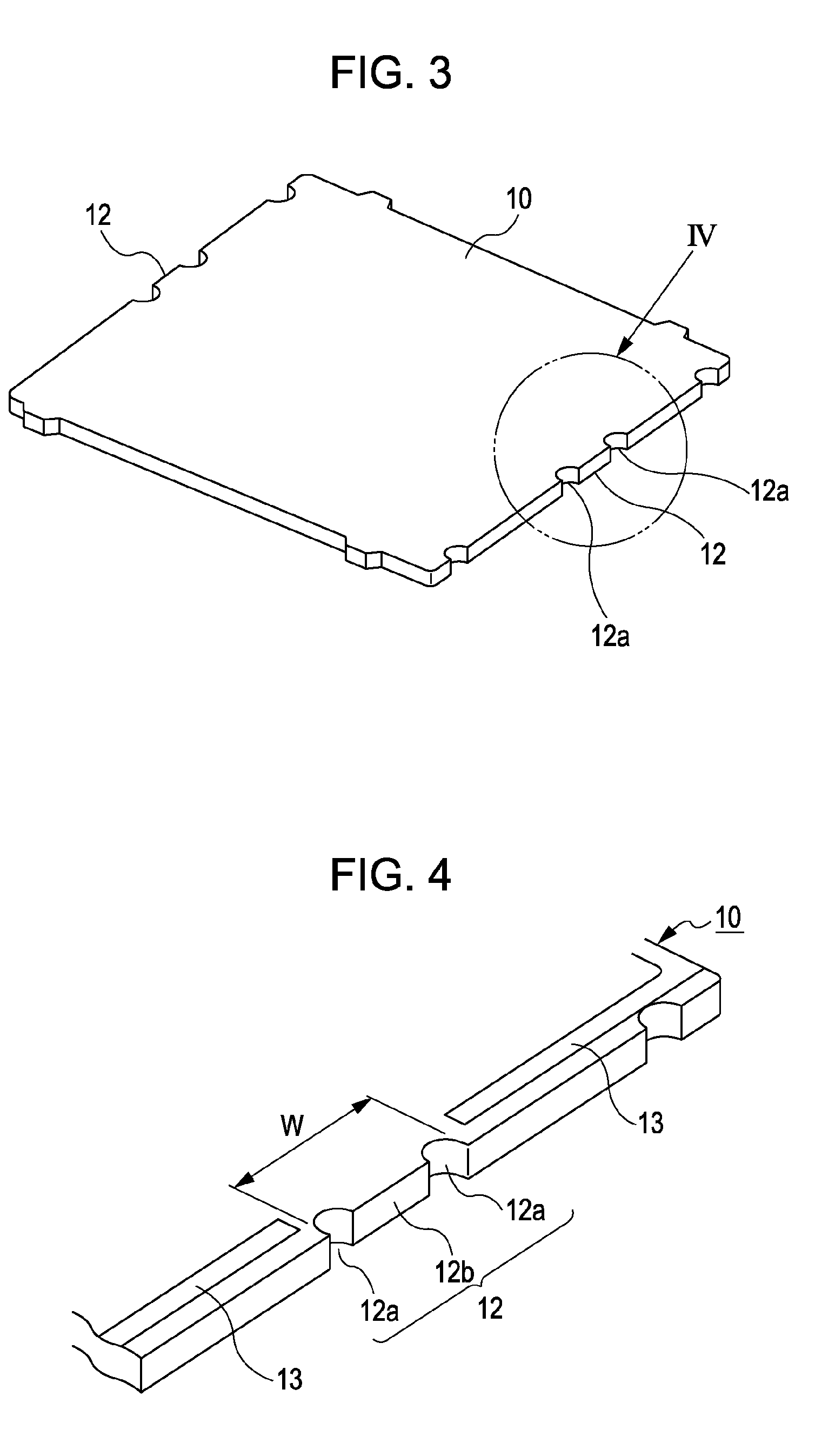
[0025]An embodiment of the present invention will be described below with reference to the drawings. FIG. 1 is an external view of an electronic circuit module according to the embodiment of the present invention. FIG. 2 is a perspective view of a cover body included in the electronic circuit module as viewed from the underside thereof. FIG. 3 is a perspective view of a circuit substrate included in the electronic circuit module as viewed from the upper side thereof. FIG. 4 is an enlarged view of section IV in FIG. 3. FIG. 5 illustrates a large board used for obtaining the circuit substrate in a plurality. FIG. 6 is a perspective view of section VI in FIG. 1 as viewed from the underside. FIG. 7 is a bottom view that corresponds to FIG. 6.

[0026]The electronic circuit module shown in FIG. 1 is formed by attaching a box-shaped cover body 11 made of a metallic plate onto a substantially rectangular circuit substrate 10 which is a resin substrate of, for example, phenol resin. The cover ...


PUM


Abstract

An electronic circuit module includes a circuit substrate whose two opposite side surfaces are provided with cutout portions; and a box-shaped cover body made of a metallic plate and having two claw segments individually disposed within the cutout portions, the cover body being attached to the circuit substrate so as to cover the top surface thereof. The circuit substrate has notches extending linearly inward beyond the opposite ends of each cutout portion from the corresponding side surface of the circuit substrate. The opposite ends of each claw segment in the width direction thereof are disposed facing linear sections of the corresponding notches within the corresponding cutout portion.

Description

CLAIM OF PRIORITY[0001]This application claims benefit of the Japanese Patent Application No. 2007-259972 filed on Oct. 3, 2007, which is hereby incorporated by reference.BACKGROUND OF THE INVENTION[0002]1. Field of the Invention[0003]The present invention relates to an electronic circuit module formed by attaching a cover body made of a metallic plate to a circuit substrate, and particularly, to an electronic circuit module having a structure in which the cover body and the circuit substrate are positioned with respect to each other by disposing claw segments of the cover body within cutout portions provided in the side surfaces of the circuit substrate.[0004]2. Description of the Related Art[0005]With regard to wireless communication devices, for example, there are cases where these devices employ an electronic circuit module having a structure in which a cover body, such as a shield casing made of a metallic plate, is attached to a circuit substrate equipped with high-frequency c...

Claims


Application Information

Patent Timeline
IPC IPC(8): H05K1/02
CPCH05K3/3405H05K2201/10371H05K2201/09145H05K9/00H05K5/03
Inventor WATANABE, YOSHIKIYO
Owner ALPS ALPINE CO LTD
Why Eureka
Eureka Blog
Learn More