Eureka AIR delivers breakthrough ideas for toughest innovation challenges, trusted by R&D personnel around the world.

Webbing take-up device

Active Publication Date: 2013-10-03
KK TOKAI RIKA DENKI SEISAKUSHO
View PDF14 Cites 6 Cited by
  • Summary
  • Abstract
  • Description
  • Claims
  • Application Information

AI Technical Summary

Benefits of technology

The present invention is a webbing take-up device that includes a restriction member to maintain meshing between gears and prevent displacement of the sun gear. The restriction member interferes with the sun gear from the opposite side, effectively suppressing displacement. The device is easy to assemble and can suppress axial wobbling of the sun gear.

Problems solved by technology

It is accordingly difficult to achieve a small size for each of the gears.
However, it is difficult to mesh the planet gears properly with both the sun gear and the internal-toothed gear without both appropriate rotation positions of the planet gears about their respective axial centers and appropriate rotation positions of the planet gears about the sun gear.
In particular, in a case in which plural planet gears are employed, assembly is difficult from the second planet gear (and the subsequent planet gears).

Method used


Image

  • Webbing take-up device
  • Webbing take-up device
  • Webbing take-up device

Examples


Embodiment Construction

Configuration of an Exemplary Embodiment

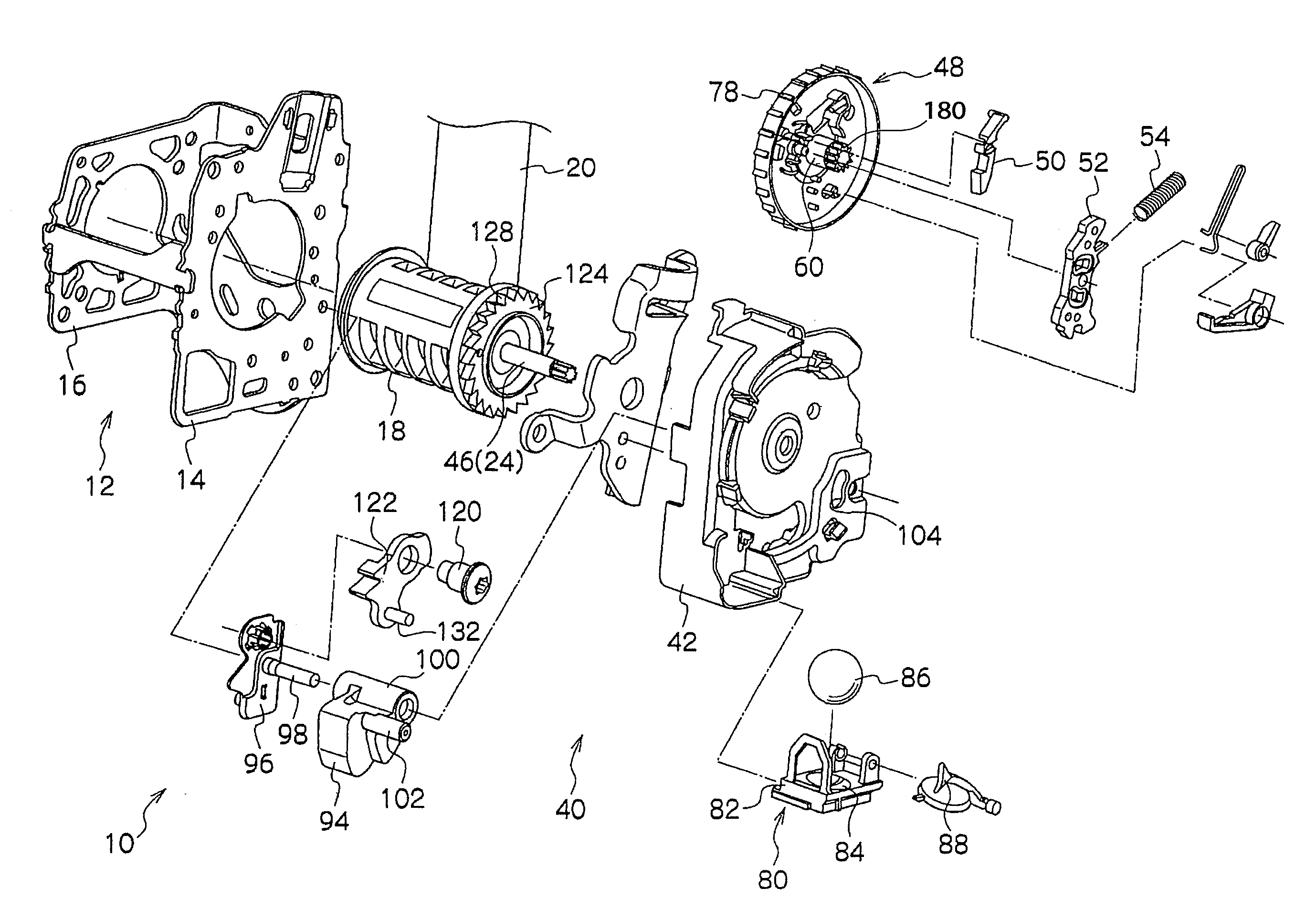
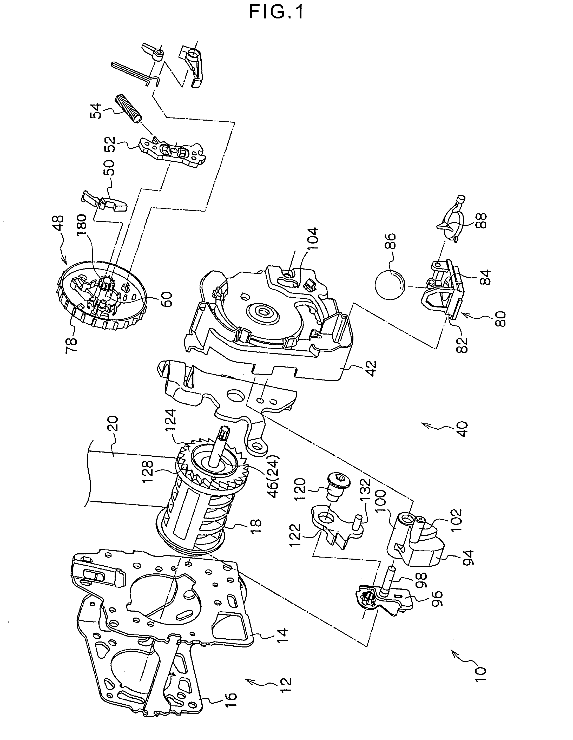
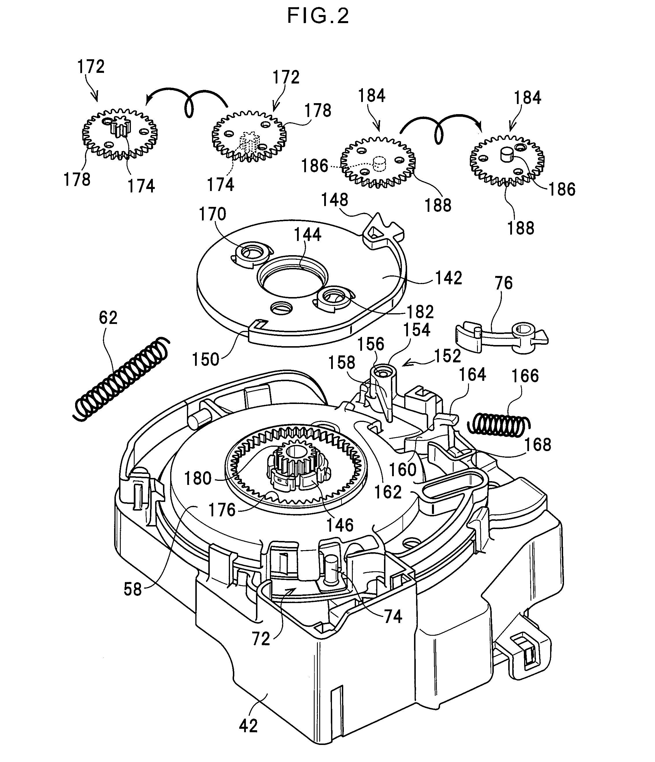
[0036]FIG. 1 is an exploded perspective view illustrating an outline configuration of a webbing take-up device 10 according to an exemplary embodiment of the present invention. As a continuation of the configuration illustrated in FIG. 1, FIG. 2 is an exploded perspective view illustrating the configuration of relevant portions of the webbing take-up device 10.

[0037]As shown in FIG. 1, the webbing take-up device 10 is provided with a frame 12. The frame 12 is provided with for example a pair of leg plates 14, 16 that face each other substantially along the vehicle front-rear direction. A spool 18 is provided between the leg plate 14 and the leg plate 16. The spool 18 is formed in a substantially circular cylindrical shape with the axial direction aligned along the facing direction of the leg plates 14, 16.

[0038]A length direction base end side of an elongated strap shaped webbing 20 is anchored to the spool 18. The webbing 20 is taken up and s...


PUM


Abstract

A restriction rotating body is provided at a carrier plate, on the opposite side of a sun gear to a planet gear. When an internal-toothed gear is displaced together with a sensor gear in the rotation radial direction thereof, the internal-toothed gear presses a shaft portion of the restriction rotating body, and further, a gear portion of the restriction rotating body presses the sun gear. Due thereto, the amount of relative displacement of the internal-toothed gear with respect to the sun gear can accordingly be reduced. Moreover, since the restriction rotating body does not mesh with the internal-toothed gear, the restriction rotating body can be easily assembled after assembly of the planet gear. The planet gear can accordingly be easily assembled prior to assembly of the restriction rotating body.

Description

CROSS-REFERENCE TO RELATED APPLICATION[0001]This application claims priority under 35 USC 119 from Japanese Patent Application No. 2012-082809 filed Mar. 30, 2012, the disclosure of which is incorporated by reference herein.BACKGROUND OF THE INVENTION[0002]1. Field of the Invention[0003]The present invention relates to a webbing take-up device that takes up and stores webbing.[0004]2. Related Art[0005]A webbing take-up device configuring a vehicle seatbelt device is equipped with a locking mechanism such as an emergency locking retractor (this type of locking mechanism is referred to below as an “ELR mechanism”) that is actuated to restrict rotation of a spool in a pull-out direction when the vehicle decelerates suddenly, or when the spool that takes up and stores the webbing is rotated sharply in the pull-out direction. There is also a locking mechanism such as an automatic locking retractor (this type of locking mechanism is referred to below as an “ALR mechanism”) that, unlike th...

Claims


Application Information

Patent Timeline
IPC IPC(8): B60R22/415
CPCB60R22/415
Inventor YANAGAWA, WATARUUKITA, MASARUTAKAMATSU, HITOSHI
Owner KK TOKAI RIKA DENKI SEISAKUSHO
Why Eureka
Eureka Blog
Learn More