Coil-incorporated component

Inactive Publication Date: 2018-09-06
MURATA MFG CO LTD
View PDF0 Cites 7 Cited by
  • Summary
  • Abstract
  • Description
  • Claims
  • Application Information

AI Technical Summary

Benefits of technology

[0022]According to this configuration, in the inner side portion of the first coil pattern and in the inner side portion of the fourth coil pattern, a magnetic flux along the coil axis is not interfered with by the intermediate layer, and thus, the magnetic field coupling b

Problems solved by technology

However, in a case in which the number of laminated layers is simply increased, the inductance value can be increased, but the magnetic field coupling between the two coil elements cannot be improved.
In other words, in a structure in which the first coil element and the

Method used


Image

  • Coil-incorporated component
  • Coil-incorporated component
  • Coil-incorporated component

Examples


first preferred embodiment

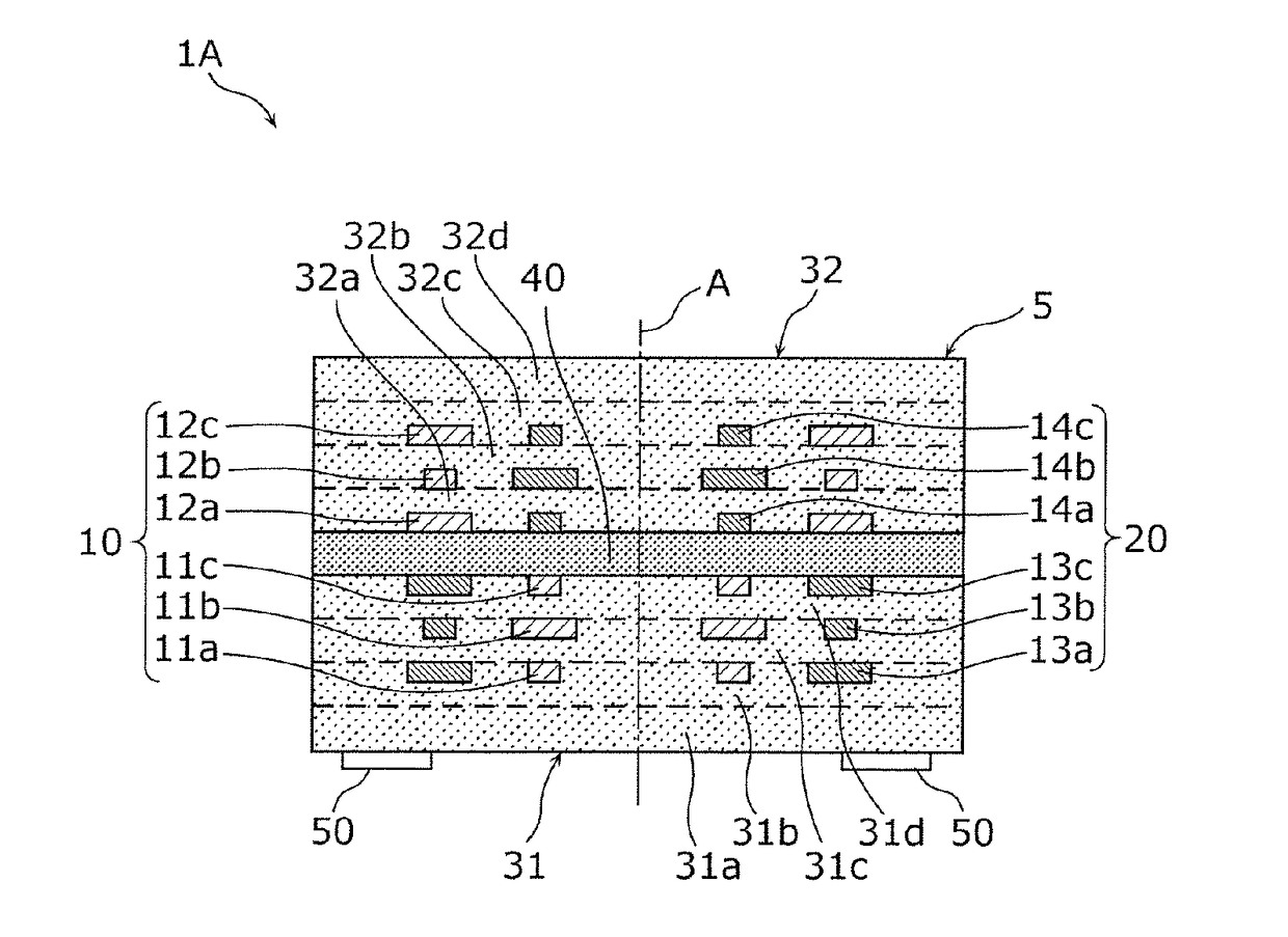
[0038]A coil-incorporated component according to a first preferred embodiment of the present invention includes two coil elements that are incorporated. This coil-incorporated component is not limited to a configuration to be incorporated in a dual inductor, such as a common mode choke coil, a transformer, a coupler, a balun, or other dual inductor, may have a configuration to be incorporated in a multilayer circuit component, such as a choke coil or other suitable coil of a multiphase DC-DC converter. The present preferred embodiment will be described using a dual inductor as an example of the coil-incorporated component.

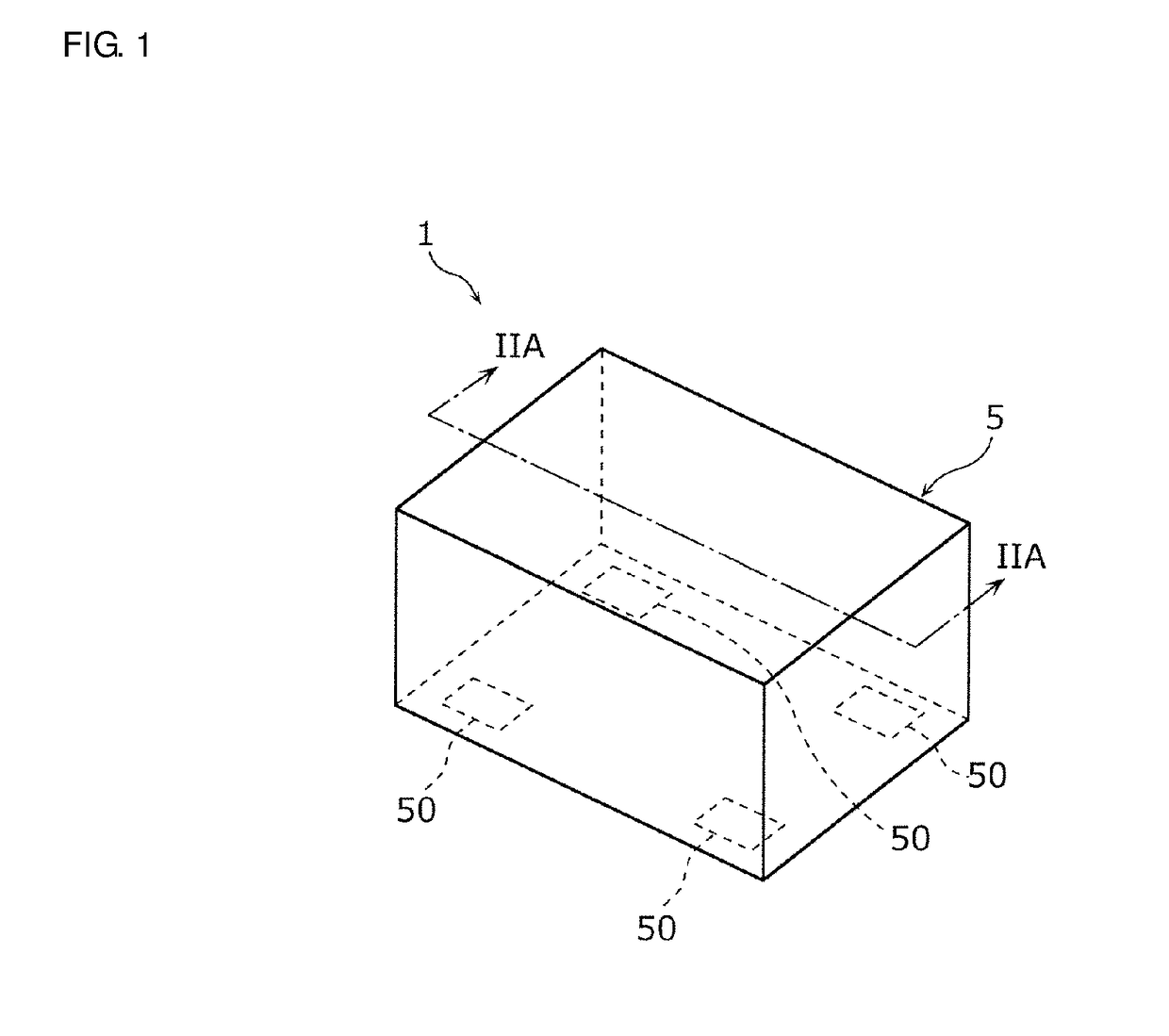
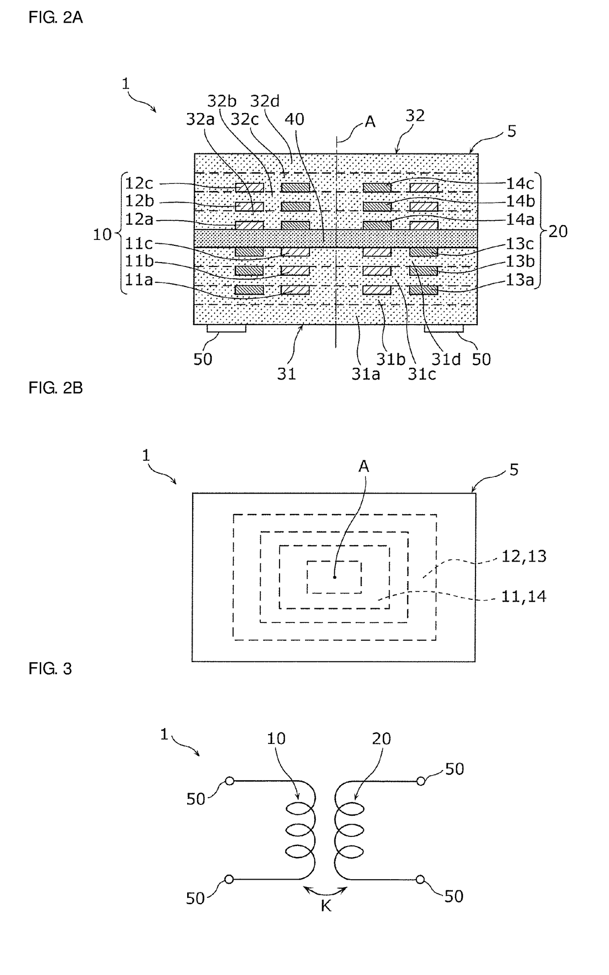
[0039]FIG. 1 is a perspective view of a coil-incorporated component 1 according to the present preferred embodiment. FIG. 2A is a cross sectional view of the coil-incorporated component 1 taken along a line IIA-IIA in FIG. 1, FIG. 2B is a diagram of the multilayer type coil-incorporated component 1 when viewed from a lamination direction. FIG. 3 illustrates an equi...

second preferred embodiment

[0075]Next, a coil-incorporated component according to a second preferred embodiment of the present invention will be described.

[0076]FIG. 6 is a schematic diagram illustrating a cross-section of a coil-incorporated component 1C according to the second preferred embodiment. FIG. 7 is a diagram illustrating magnetic body layers a to g and j to o, intermediate layers h and i, the first coil pattern 11, the second coil pattern 12, the third coil pattern 13, the fourth coil pattern 14, and routing conductor patterns p1 to p8 forming the coil-incorporated component 1C.

[0077]The coil-incorporated component 1C includes, as illustrated in FIG. 6, the multilayer element body 5 and a plurality of the external terminals 50 provided on the bottom surface of the multilayer element body 5.

[0078]In the inside of the multilayer element body 5, the first coil element 10 and the second coil element 20 are provided. The first coil element 10 includes the first coil pattern 11 (11a, 11b, 11c, 11d, and ...

third preferred embodiment

[0103]Next, a coil-incorporated component 1D according to a third preferred embodiment of the present invention will be described.

[0104]FIG. 8 is a schematic diagram illustrating a cross-section of the coil-incorporated component 1D. FIG. 9 illustrates an equivalent circuit of the coil-incorporated component 1D.

[0105]In the coil-incorporated component 1D according to the third preferred embodiment, external terminals 53 and 54 are provided on the bottom surface of the multilayer element body 5, are external terminals 51 and 52 are provided on a top surface which is a surface opposite from the bottom surface. The external terminal 51 is connected to one end and the external terminal 52 is connected to the other end of the first coil element 10. Additionally, the external terminal 53 is connected to one end and the external terminal 54 is connected to the other end of the second coil element 20.

[0106]In the coil-incorporated component 1D, when viewed from the lamination direction, the...


PUM


Abstract

A coil-incorporated component includes a first coil element including a first coil pattern and a second coil pattern, and a second coil element including a third coil pattern and a fourth coil pattern. The first coil pattern and the third coil pattern are provided in a first base material layer, the second coil pattern and the fourth coil pattern are provided in a second base material layer. When a coil-incorporated component is viewed from a lamination direction, the first coil pattern and the fourth coil pattern at least partially overlap with each other, the second coil pattern and the third coil pattern at least partially overlap with each other. An intermediate layer having a low magnetic permeability is provided between the first coil pattern and the fourth coil pattern and between the second coil pattern and the third coil pattern.

Description

CROSS REFERENCE TO RELATED APPLICATIONS[0001]This application claims the benefit of priority to Japanese Patent Application No. 2015-252656 filed on Dec. 24, 2015 and is a Continuation Application of PCT Application No. PCT / JP2016 / 088254 filed on Dec. 21, 2016. The entire contents of each application are hereby incorporated herein by reference.BACKGROUND OF THE INVENTION1. Field of the Invention[0002]The present invention relates to a coil-incorporated component, and particularly, to a multilayer type coil-incorporated component in which two coil elements are incorporated.2. Description of the Related Art[0003]An existing coil-incorporated component with two coil elements formed in a multilayer substrate is known (for example, see Japanese Unexamined Patent Application Publication No. 2015-73052).[0004]A coil-incorporated component disclosed in Japanese Unexamined Patent Application Publication No. 2015-73052 includes a multilayer element body formed by laminating a plurality of mag...

Claims


Application Information

Patent Timeline
IPC IPC(8): H01F27/28H01F27/32H01F27/24
CPCH01F27/2804H01F27/323H01F27/24H01F2027/2809
Inventor YAZAKI, HIROKAZU
Owner MURATA MFG CO LTD
Why Eureka
Try Eureka