Stress evaluation program for mobile terminal and mobile terminal provided with program

a mobile terminal and stress evaluation technology, applied in the field of stress evaluation programs, can solve the problems of inability to visually recognize stress and inability to easily measure stress

Active Publication Date: 2018-09-06
SAITO RYOZO +3
View PDF10 Cites 8 Cited by
  • Summary
  • Abstract
  • Description
  • Claims
  • Application Information

AI Technical Summary

Benefits of technology

[0020]This disclosure provides a technique applied to a mobile terminal device for measuring the state of stress based on the objective symptoms associated with stress.

Problems solved by technology

However, in general, the stress cannot be visually recognized and is not easily measured by a device or the likes.

Method used


Image

  • Stress evaluation program for mobile terminal and mobile terminal provided with program
  • Stress evaluation program for mobile terminal and mobile terminal provided with program
  • Stress evaluation program for mobile terminal and mobile terminal provided with program

Examples


first embodiment

SUMMARY

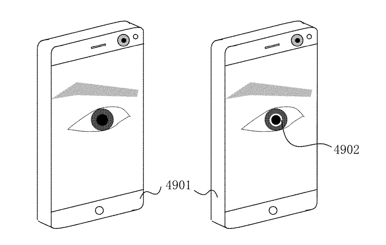
[0082]A program according to an embodiment of this disclosure is recorded and readable by a mobile terminal device, and the mobile terminal device reads and executes the program to capture the moving image of the pupil change when irradiated by light, and to calculate the pupil change of the obtained image over time. In addition, a mobile terminal device that reads and executes the recorded program is also provided. The mobile terminal device can be a mobile terminal or other terminals, such as a desktop computer. In the following embodiments, the mobile terminal device is a mobile terminal for an example.

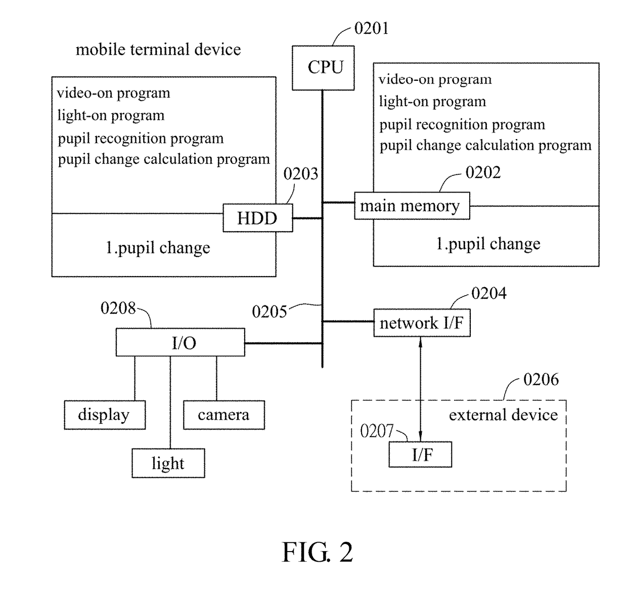
[0083]The function and hardware of the mobile terminal device and the processing procedure of this embodiment will be described hereinafter.

[0084]

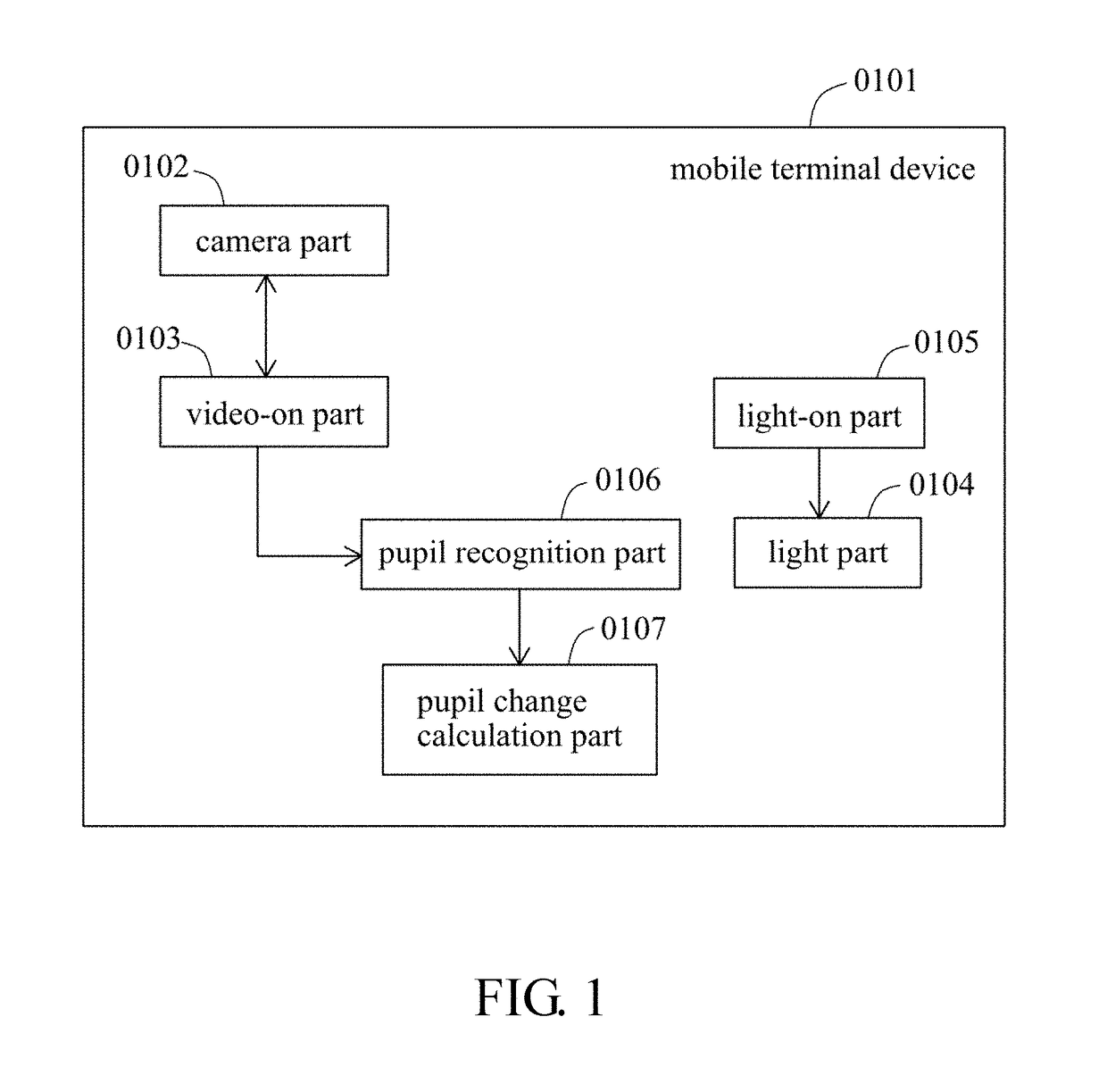
[0085]FIG. 1 is a functional block diagram of a mobile terminal device according to an embodiment. As shown in FIG. 1, the mobile terminal device (0101) of this embodiment includes a camera part (0102), a video-on part (0103), a li...

second embodiment

[0156]

[0157]In this embodiment, in addition to the configuration of the first embodiment, as a more preferable embodiment, the mobile terminal device further having a function of changing illuminance of a light over time is provided.

[0158]Hereinafter, the function of the device, the contents of the hardware in this embodiment, and the processing flow will be described in detail.

[0159]

[0160]FIG. 4 is a diagram showing an example of functional blocks of the mobile terminal device of this embodiment. As shown in the figure, the mobile terminal device (0401) of the present embodiment includes a camera part (0402), a video-on part (0403), a light part (0404), a light-on part (0405), a pupil recognition part (0406), a pupil change calculation part (0407), and an illuminance changing part (0408). The feature of this embodiment lies in the content of the illuminance changing part. Therefore, the functional configuration of the illuminance changing part will be mainly described. Since the ot...

third embodiment

[0178]

[0179]This embodiment is a more preferable embodiment providing a mobile terminal device having a function of evaluating the stress level in addition to any one of the configurations of the first and second embodiments.

[0180]Hereinafter, the function of the device, the contents of the hardware, and the processing flow of this embodiment will be described in detail.

[0181]

[0182]FIG. 7 is a diagram showing an example of functional blocks of the mobile terminal device of this embodiment. As shown in the figure, the mobile terminal device (1001) of this embodiment includes a camera part (1002), a video-on part (1003), a light part (1004), a light-on part (1005), a pupil recognition part (1006), a pupil change calculation part (1007), and a stress evaluation part (1008). The feature of the present embodiment lies in the content of the stress evaluation part. Therefore, the functional configuration of the stress evaluation part will be mainly described. Since the other functions are ...


PUM


Abstract

To provide a technique for measuring a state of stress by objective symptoms having a correlation with stress in a mobile terminal device. In order to the above object, a program is provided, and a mobile terminal device reads and executes the program to perform: a video-on step for enabling a moving image capturing function of the mobile terminal; a light-on step for enabling a light disposed at an image capturing side of the mobile terminal; a pupil recognition step for recognizing pupils of animal eyes from an image that is being captured, wherein the animal eyes include human eyes; and a pupil change calculation step for calculating a pupil change, wherein the pupil change is a change in a dilation level of the recognized pupil over time.

Description

BACKGROUNDTechnology Field[0001]This disclosure relates to a stress evaluation program applied to a mobile terminal.Description of Related Art[0002]The stress is the reason for causing various diseases. However, in general, the stress cannot be visually recognized and is not easily measured by a device or the likes.[0003]Therefore, the preferred technique is to measure the state of stress based on the objective symptoms associated with stress.[0004]The above technique can be referred to those disclosed in the following references.REFERENCE OF CONVENTIONAL ARTPatent Reference[0005]Patent reference 1: JP Patent Application No. 2005-143684SUMMARYThe Problem to be Solved by this Invention[0006]The above patent reference is to find the correlation between the stress or relaxation level and the pupil response to light. The concept of this reference is to capture the image of eyes and analyze the pupil response to light irradiation so as to measure the stress level. According to this conce...

Claims


Application Information

Patent Timeline
Patent Type & Authority Applications(United States)
IPC IPC(8): H04M1/725G06T7/20G16H50/20G16H30/40G06K9/00G06F9/44G06F17/18
CPCH04M1/72522G06T7/20G16H50/20G16H30/40G06K9/00604G06F9/44G06F17/18A61B3/11A61B5/16G06T7/0016G06T2207/10016G06T2207/10024G06T2207/10152G06T2207/30041G06F9/445G06F9/451G16H40/63A61B5/163G06V40/19G06F2218/12
Inventor SAITO, RYOZO
Owner SAITO RYOZO
Why Eureka
Try Eureka