
A stress evaluation method and a stress evaluation system

A technology of stress and secondary stress, applied in the field of stress evaluation method and stress evaluation system, can solve problems such as indistinguishability, large equipment thickness, and strength failure, so as to avoid cost increase, ensure qualified strength, and improve safety performance

Inactive Publication Date: 2019-01-29
YANSHAN UNIV
View PDF5 Cites 2 Cited by
  • Summary
  • Abstract
  • Description
  • Claims
  • Application Information

AI Technical Summary

Problems solved by technology

[0003] Due to the discontinuous structure of the connection area between the connecting pipe and the shell, the finite element stress analysis software cannot distinguish the primary stress and secondary stress components in the film plus bending stress extracted from the calculation results. If the film plus bending stress is evaluated according to the primary stress intensity (The limit is 1.5 times the allowable stress), which will cause the final thickness of the equipment to be larger than required, and the waste is serious; if it is evaluated according to the secondary stress intensity (the limit is 3 times the allowable stress), the primary stress Omission of evaluation makes the calculation structure unsafe, and the actual product is prone to safety accidents
At present, there is no safe way to deal with it. In many cases, only a compromise of 2.2 times the allowable stress is used as the evaluation standard. There is no theoretical basis. Using this kind of treatment method will lead to excessive thickness of some equipment, resulting in unnecessary cost increase, while others On the one hand, it may also cause insufficient thickness of some equipment, which may cause strength failure

Method used


Image

  • A stress evaluation method and a stress evaluation system
  • A stress evaluation method and a stress evaluation system
  • A stress evaluation method and a stress evaluation system

Examples


Embodiment Construction

[0047] The following will clearly and completely describe the technical solutions in the embodiments of the present invention with reference to the accompanying drawings in the embodiments of the present invention. Obviously, the described embodiments are only some, not all, embodiments of the present invention. Based on the embodiments of the present invention, all other embodiments obtained by persons of ordinary skill in the art without making creative efforts belong to the protection scope of the present invention.

[0048] The purpose of the present invention is to provide a stress evaluation method and a stress evaluation system, which can effectively ensure that the strength of the pressure vessel is qualified, and at the same time avoid unnecessary cost increases. , can further improve the safety performance of the pressure vessel.

[0049] In order to make the above objects, features and advantages of the present invention more comprehensible, the present invention wi...


PUM


Abstract

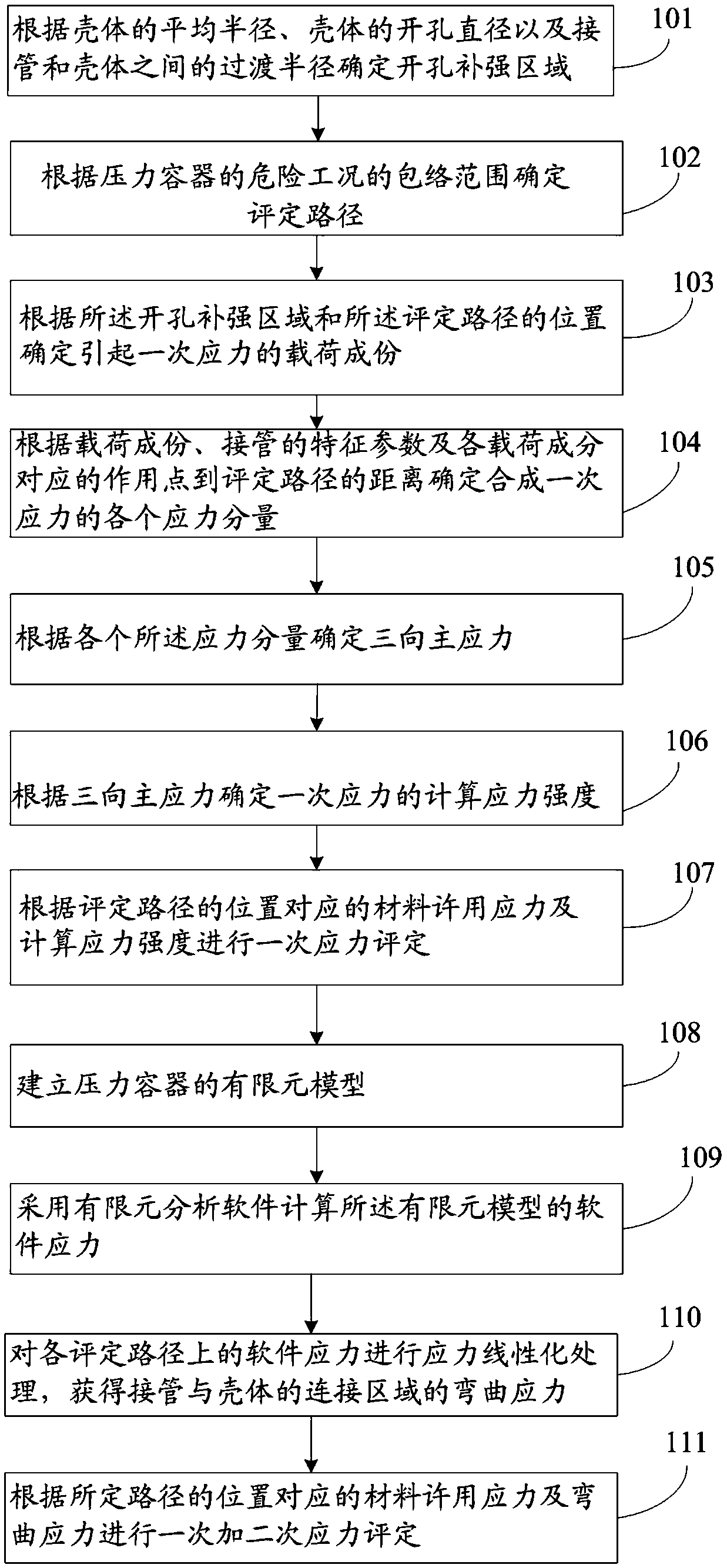
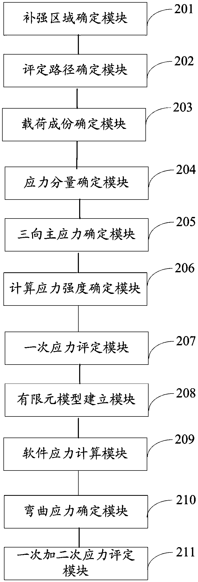
The invention discloses a stress evaluation method and a stress evaluation system. At first, accord to that load component causing the primary stress in the connected area between the nozzle and the shell, the characteristic parameter of the nozzle and the distance from the action point corresponding to each load component to each evaluation path, each stress component of the composite primary stress is determined; then, the three-dimensional principal stress is determined according to each stress component, and the calculated stress intensity of the primary stress is determined according to the three-dimensional principal stress. Finally, according to the allowable stress of the material corresponding to the position of the evaluation path and the calculated stress intensity, the joint area of the nozzle and the shell is evaluated once. The invention takes the dangerous path as the evaluation path, and evaluates the different stress components caused by different loads accordingly, soas to effectively ensure that the strength of the pressure vessel is qualified and avoid unnecessary cost increase at the same time. On this basis, the stability of the pressure vessel can be ensuredby combining the primary and secondary stress assessment of the connecting area between the nozzle and the shell.

Description

technical field [0001] The invention relates to the field of pressure vessels, in particular to a stress evaluation method and a stress evaluation system. Background technique [0002] Pressure vessels are widely used in petrochemical, energy power, oil and gas storage and transportation, thermal power and nuclear power equipment. The connection between the connection pipe and the shell is a typical structure. For this part, finite element stress analysis software such as Ansys is often used for analysis. Calculate, and then carry out stress assessment on this part according to the design stress intensity stipulated in the standard, that is, the allowable value. [0003] Due to the discontinuous structure of the connection area between the connecting pipe and the shell, the finite element stress analysis software cannot distinguish the primary stress and secondary stress components in the film plus bending stress extracted from the calculation results. If the film plus bendi...

Claims


Application Information

Patent Timeline
IPC IPC(8): G06F17/50
CPCG06F30/17G06F30/23G06F2119/06
Inventor 曹丽琴张红升
Owner YANSHAN UNIV
Learn More