Method for whole field thin film stress evaluation

a stress evaluation and thin film technology, applied in the direction of force measurement by measuring optical property variation, force/torque/work measurement apparatus, instruments, etc., can solve problems such as ghost image production, optical system performance regression, and failure to opera

Active Publication Date: 2008-07-22
NAT APPLIED RES LAB
View PDF3 Cites 2 Cited by
  • Summary
  • Abstract
  • Description
  • Claims
  • Application Information

AI Technical Summary

Problems solved by technology

The thin film would be possibly peeled off from the substrate, crack or wrinkle may occur while the stress existing therein is relatively large.
In addition, damaged optical film may introduce unexpected scattering beams into optical system, which may lead to the production of ghost image.
The optical system may thus suffer performance regression and even fail in operation.
Generally, optical elements of a relatively high power are always adopted in a typical liquid crystal projector for achieving the high illumination, which brings the optical engine to be operated under a high temperature, so that the optical thin film or the optical coating would be easily peeled off or damaged due to the high temperature thereof.
In this case, the liquid crystal projector may be disadvantageous in conducting a reduced illumination and a non-uniform lightness, and the ghost image produced owing to the damaged optical thin film therein also decreases the performance thereof.
Therefore, it becomes a critical issue in this field to evaluate the ability in estimating the stress introduced by deposited thin film thereof.
Such a method, however, is not suitable for an amorphous film.
Nevertheless, the mentioned methods adopt the phase information regarding the whole field only for precisely evaluating the average stress of the film, which still fail to provide a method for a whole field stress evaluation for the thin film.
Furthermore, the region where the film is peeled off or cracks is initialized always a region of an local extreme high stress, rather than the region of an average stress, and thus the mentioned methods are not suitable for the crack or peel-off location prediction and / or evaluation for thin film.

Method used


Image

  • Method for whole field thin film stress evaluation
  • Method for whole field thin film stress evaluation
  • Method for whole field thin film stress evaluation

Examples


Embodiment Construction

[0032]The present invention will now be described more specifically with reference to the following embodiments. It is to be noted that the following descriptions of preferred embodiments of this invention are presented herein for purpose of illustration and description only; it is not intended to be exhaustive or to be limited to the precise form disclosed.

[0033]First, the theoretical basis for the method according to the present invention is provided.

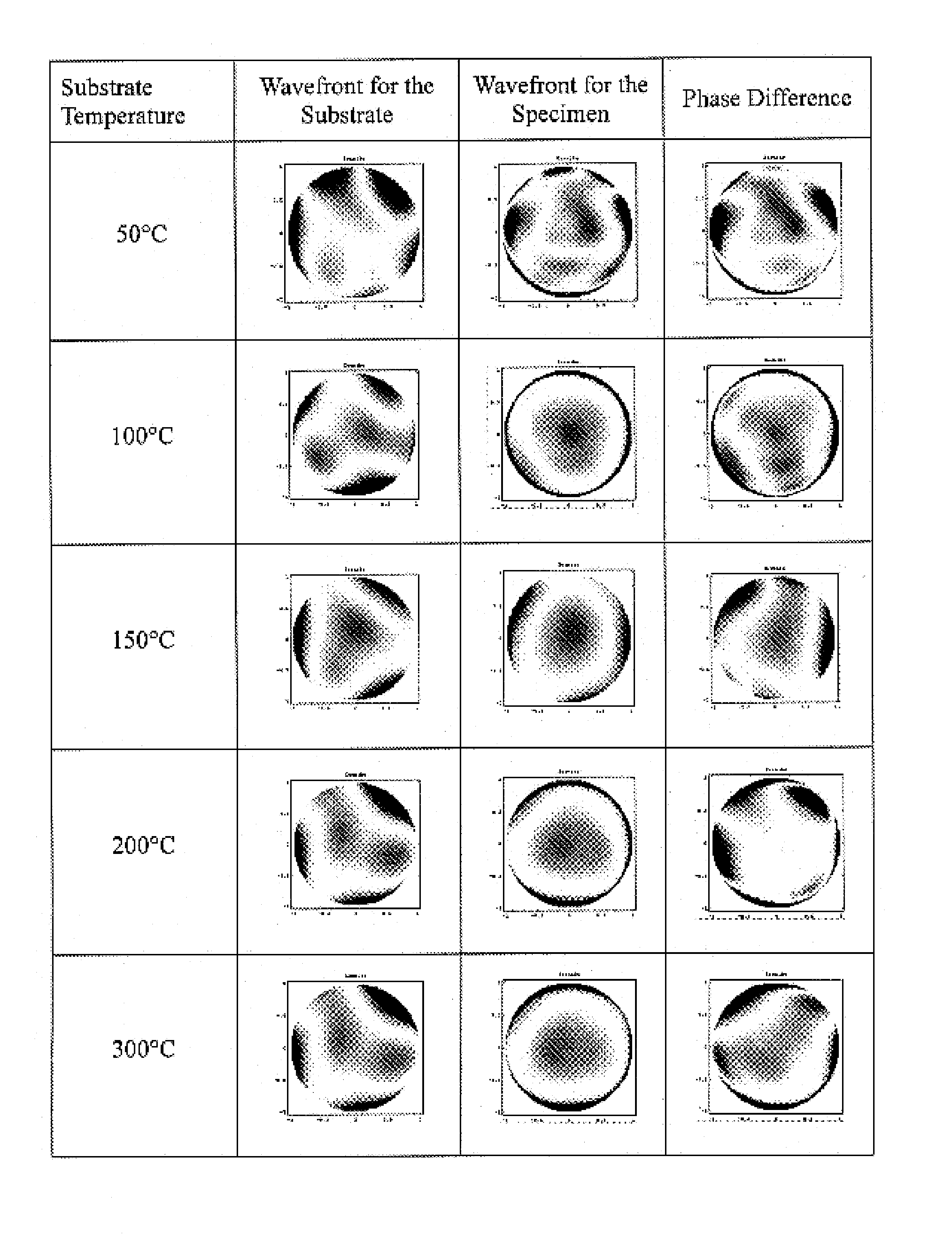
[0034]The thin film stress that is extremely produced while a thin film is deposited on a substrate typically results from the deformation limitation occurring at the interface of the substrate and the thin film, where the magnitude thereof depends on the combination of the substrate-film structure as well as the method adopted for deposition. There would be a lot of voids or cracks produced at the interface of the thin film and the substrate, and even the thin film would be easily peeled off from the substrate, if the thin film stres...


PUM

PropertyMeasurementUnit
thicknessaaaaaaaaaa
diameteraaaaaaaaaa
wavelengthaaaaaaaaaa

Abstract

A novel method for whole field thin film stress evaluation is provided. Through the provided method, the whole filed thin film stress distribution for an optical thin film would be developed with a commercial interferometer, so that a whole field evaluation for the crack or peel-off of thin film is hence achievable.

Description

FIELD OF THE INVENTION[0001]The present invention relates to a method for evaluating the stress in a thin film, and more particularly to a method for evaluating the whole field stress in a thin film.BACKGROUND OF THE INVENTION[0002]Thin film stress is regarded as a quite important factor in the thin film deposition. The thin film would be possibly peeled off from the substrate, crack or wrinkle may occur while the stress existing therein is relatively large. In addition, damaged optical film may introduce unexpected scattering beams into optical system, which may lead to the production of ghost image. The optical system may thus suffer performance regression and even fail in operation. Moreover, the performance of the deposited thin film in an electro-optics device under a critical operating condition shall be also taken into consider. Generally, optical elements of a relatively high power are always adopted in a typical liquid crystal projector for achieving the high illumination, ...

Claims


Application Information

Patent Timeline
Patent Type & Authority Patents(United States)
IPC IPC(8): G01L1/24G01B11/02
CPCG01L5/0047
Inventor HUANG, CHI HUNGYOU, HSIEN-ISHIH, MAO-YUANCHEN, CHIEN-JEN
Owner NAT APPLIED RES LAB
Why Eureka
Try Eureka