Orbital angular momentum microlaser and method

a microlaser and orbital angular momentum technology, applied in the field of micro, can solve the problems of not easily scalable and integratable, and remains a grand challenge to integrate the existing approaches

Inactive Publication Date: 2018-09-13
THE RES FOUND OF STATE UNIV OF NEW YORK
View PDF0 Cites 18 Cited by
  • Summary
  • Abstract
  • Description
  • Claims
  • Application Information

AI Technical Summary

Benefits of technology

[0010]In another aspect, a method of producing an orbital angular momentum (“OAM”) laser emission is provided. The method includes creating a first whisper-gallery mode (“WGM”) and a second WGM in a microring resonator using a pump beam. The first WGM and second WGM are counter-propagating within the resonator. The first WGM is caused to become suppressed by creating an exceptional point. The exceptional point may be crea

Problems solved by technology

Nevertheless, it remains a grand challenge to integrate the existing approaches for OAM microlasers on-a-chip.
Despite being straightforward,

Method used


Image

  • Orbital angular momentum microlaser and method
  • Orbital angular momentum microlaser and method
  • Orbital angular momentum microlaser and method

Examples


Embodiment Construction

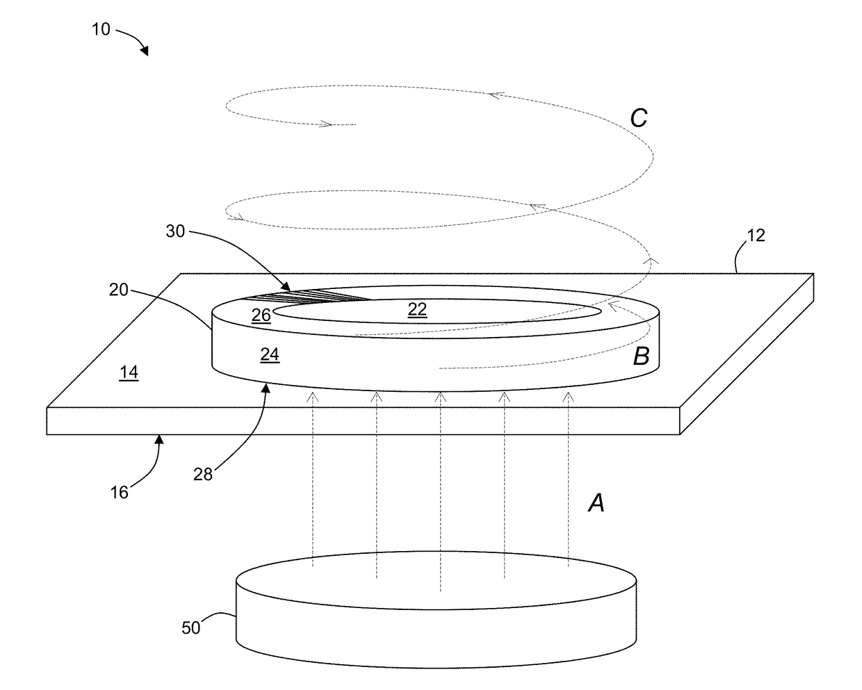
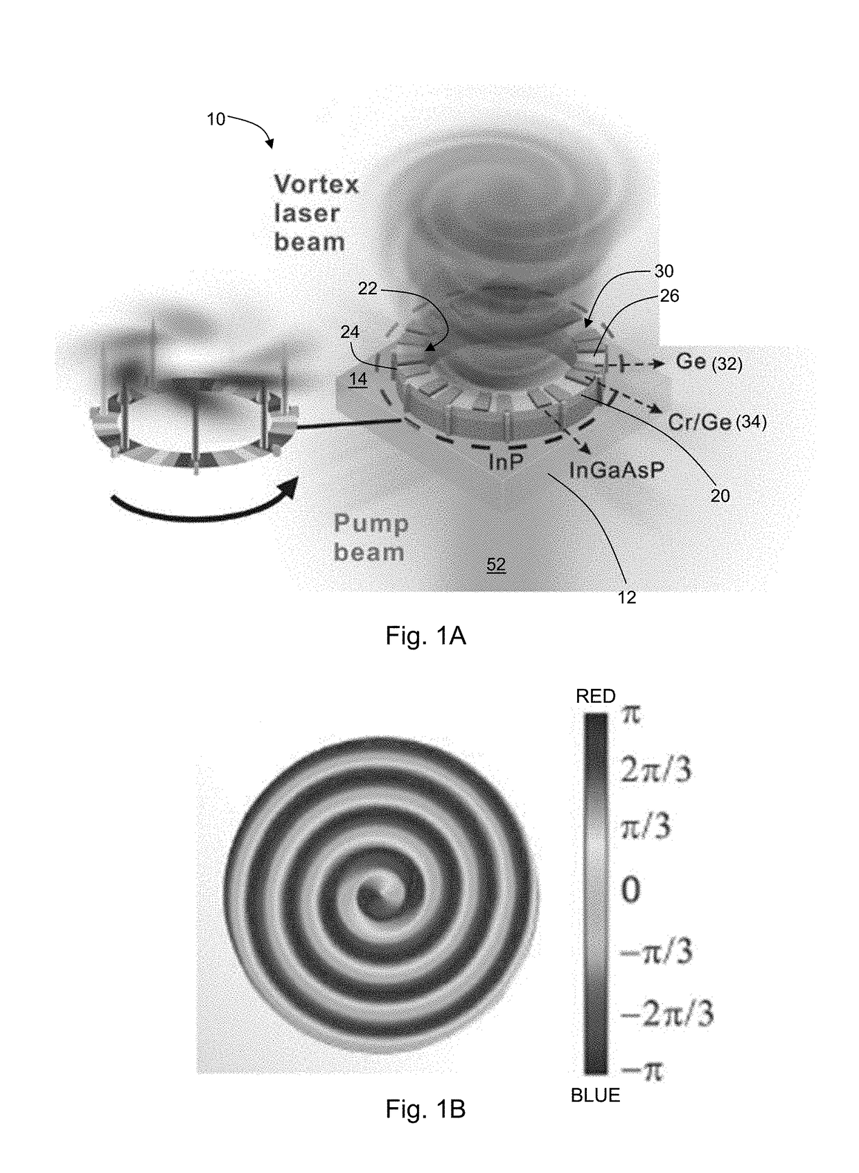
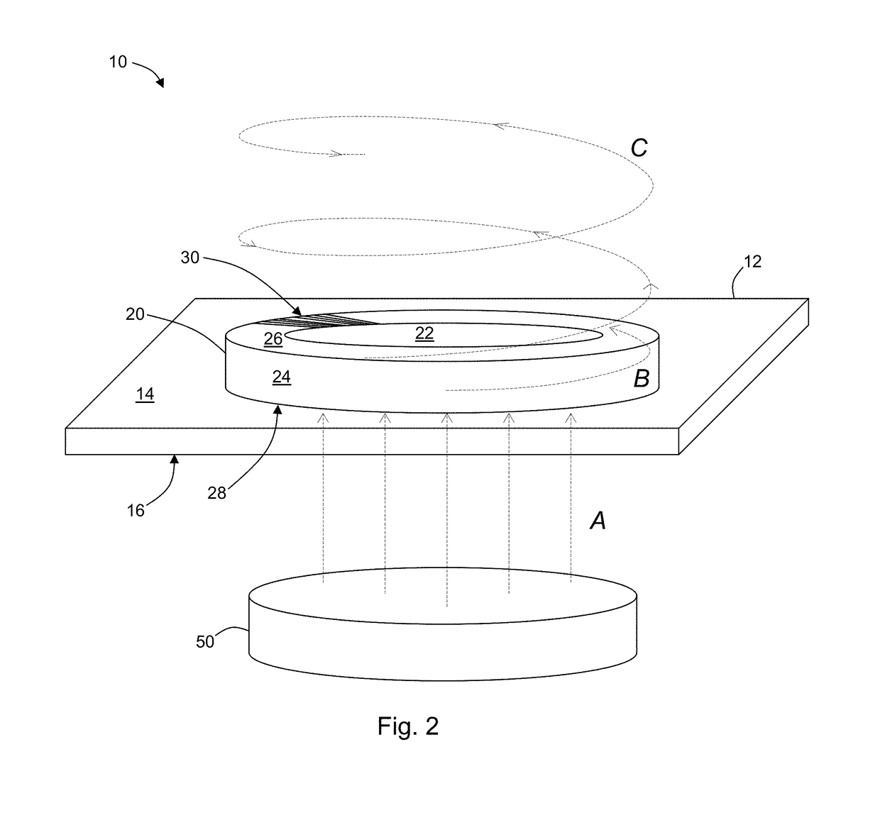
[0027]With reference to FIGS. 1A and 2, the present disclosure may be embodied as a device 10 (a “microlaser”) for emitting a laser beam having orbital angular momentum (“OAM”). The device 10 has a microring resonator 20 made of a gain medium. For example, microring resonator 20 may be made from, for example, indium gallium arsenide phosphide (InGaAsP), indium gallium arsenide (InGaAs), aluminum gallium arsenide (AlGaAs), or strained germanium (Ge). In some embodiments, the device 10 includes a substrate 12, and the microring resonator 20 is disposed on a first surface 14 of the substrate 12. The substrate 12 may be made from, for example, indium phosphide (InP).

[0028]The microring resonator 20 has a top surface 26, a bottom surface 28 opposite the top surface 26, an inner sidewall 22, an outer sidewall 24, and a top surface 26. The outer sidewall 24 is modulated for outcoupling the emitted laser beam when the microlaser 10 is in use. For example, the modulation of the outer sidewal...


PUM


Abstract

The present disclosure describes a microring OAM laser producing an optical vortex beam with an on-demand topological charge and vector polarization states. This is enabled through combined index and gain/loss modulations at an EP, which breaks the mirror symmetry in the lasing generation dynamics and facilitates unidirectional power oscillation.

Description

CROSS-REFERENCE TO RELATED APPLICATIONS[0001]This application claims priority to U.S. Provisional Application No. 62 / 470,520, filed on Mar. 13, 2017, now pending, the disclosure of which is incorporated herein by reference.STATEMENT REGARDING FEDERALLY SPONSORED RESEARCH[0002]This invention was made with government support under contract no. W911NF-15-1-0152, DE-SC0014485, and DMR1506884 awarded by the US Army Research Office, US Department of Energy and National Science Foundation, respectively. The government has certain rights in the invention.FIELD OF THE DISCLOSURE[0003]This disclosure relates to a micro or nano-scale orbital angular momentum microlaser.BACKGROUND OF THE DISCLOSURE[0004]Light typically is a stream of linearly polarized photons, traveling in a straight line, and carrying a linear momentum. However, it has been recognized that beyond the linear momentum, circularly polarized light carries angular momentum. The angular momentum associated with the polarization deg...

Claims


Application Information

Patent Timeline
IPC IPC(8): H01S5/10H01S5/04H01S5/12
CPCH01S5/1075H01S5/041H01S5/1228H01S5/1218H01S5/3434H01S2301/16H01S2301/203
Inventor FENG, LIANGLITCHINITSER, NATALIA
Owner THE RES FOUND OF STATE UNIV OF NEW YORK
Why Eureka
Try Eureka