Braided stent with expansion ring and method of delivery

a braided stent and expansion ring technology, applied in the direction of stents, etc., can solve the problems of difficult advancing of braided stents, difficult to achieve compression or crimping, and limitations on the applicability of such stents in neurovascular surgery procedures, etc., to achieve the effect of improving ease and reliability of deploymen

Active Publication Date: 2018-09-20
DEPUY SYNTHES PROD INC
View PDF4 Cites 15 Cited by
  • Summary
  • Abstract
  • Description
  • Claims
  • Application Information

AI Technical Summary

Benefits of technology

[0010]Briefly and in general terms, the present invention provides for an improved self-expanding braided stent with one or more expansion rings, and methods of delivering the self-expanding braided stent through a delivery sheath or microcatheter to a treatment site in a patient's vasculature. The present invention provides for the addition of at least one radial expansion ring to an initial deployment end or distal end of a self-expanding braided stent to increase a radial expansion force of the self-expanding braided stent, for improved ease and reliability of deployment of the self-expanding braided stent, and particularly more reliable expansion and fixing of the initial deployment end or distal end of the self-expanding braided stent in deployment of the self-expanding braided stent. The addition of a radial expansion ring to a later deployed end or proximal end of a self-expanding braided stent allows the self-expanding braided stent to be recaptured following partial deployment of a distal portion of the self-expanding braided stent, and prior to full deployment of a later deployed portion or proximal portion of the self-expanding braided stent.

Problems solved by technology

While such procedures may be useful in certain aspects of vascular surgery in which vasoocclusive devices are used, the weakness and tortuosity of the neurovasculature places limits on the applicability of such stents in procedures to repair neurovascular defects.
Furthermore, the use of placement techniques, such as balloons or mechanical expansions of the type often found to be useful in cardiac surgery, are relatively less useful in vasoocclusive surgery, particularly when tiny vessels, such as those found in the brain, are to be treated.
However, one of the problems in deploying a self-expanding braided stent in a body lumen is activation of the initially expanding end, typically the distal end of the braided stent, to fully open.
Stents made of braided wire also commonly have a high internal friction that resists the inherent radial expansion force of the self-expanding braided stent to open, particularly resisting opening of the initially expanding end, which can cause problems in anchoring and deployment of such self-expanding braided stents.
Another common problem with deployment of braided stents is difficulty in advancing the compressed or crimped braided stent through a delivery sheath or microcatheter, typically also due to friction between the braided stent and the delivery sheath or microcatheter.
As a result, as the braided stent expands within the delivery sheath or microcatheter, an increased normal force is applied to the inner surface of the delivery sheath or microcatheter, increasing friction between the braided stent and the delivery sheath or microcatheter.
Deployment of such self-expanding braided stents commonly requires extra manipulation by a user to fully open the self-expanding braided stents, which affects placement accuracy and adds risk to the procedure.
Another problem with deployment of self-expanding braided stents involves difficulty in recapturing a self-expanding braided stent after partial deployment and prior to full deployment of the stent.

Method used


Image

  • Braided stent with expansion ring and method of delivery
  • Braided stent with expansion ring and method of delivery
  • Braided stent with expansion ring and method of delivery

Examples


first embodiment

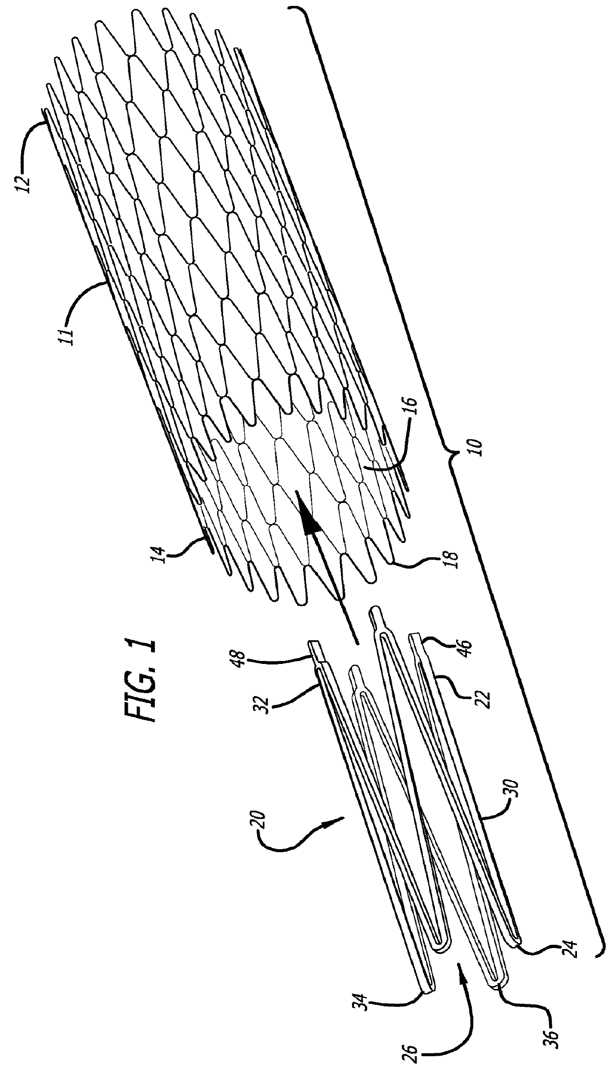
[0027]Accordingly, referring to the drawings, which are provided by way of example, and not by way of limitation, in a first embodiment, for treatment of a patient's vasculature, the present invention provides for a braided stent 10 including a tubular braided stent body 11, having a later deployed end or proximal end 12, an initial deployment end or distal end 14, and an inner lumen 16. The tubular braided stent body is preferably formed from a plurality of elongate members 18, typically formed from two or more metal wires, or polymeric fibers or strands of material, for example. In a presently preferred aspect, the braided stent is a self-expanding stent, and includes one or more expansion rings 20, each having a first end 22, a second end 24, and an inner lumen 26. The one or more expansion rings preferably are disposed within and fixedly connected to at least the initial deployment end or distal end of the tubular braided stent body, although one or more expansion rings may also...

second embodiment

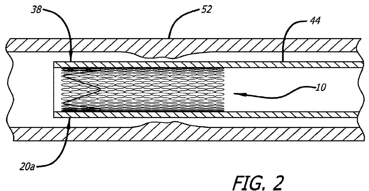
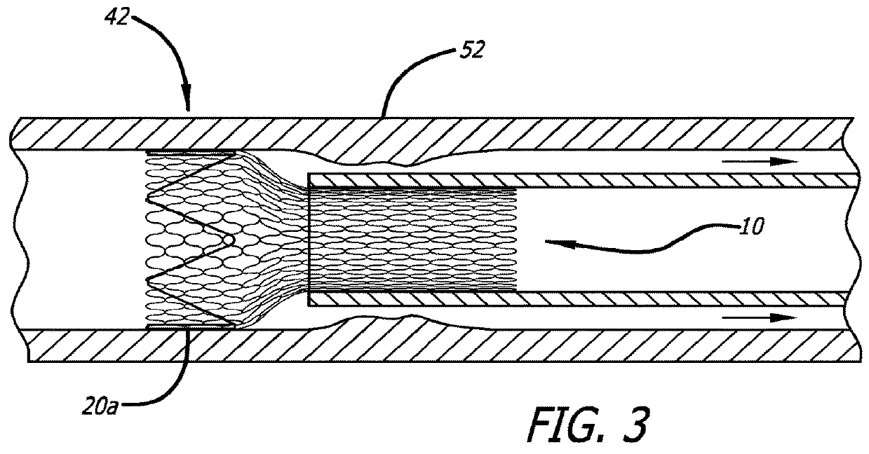
[0031]Referring to FIGS. 4-9, in a second embodiment, in which like elements are indicated by like reference numbers, the present invention further provides for an apparatus 50 for delivering and releasing a self-expanding braided stent through a delivery sheath or microcatheter to a treatment site in a patient's vasculature 52. The apparatus includes a braided stent including a tubular braided stent body, described above, and also includes a core advancement wire 54, which is disposed within and extends through the lumen of the tubular braided stent body, and is disposed within and extending through the lumen of the distal expansion ring 20a fixedly connected within the initial deployment end or distal end of the tubular braided stent body. When a proximal expansion ring 20b is fixedly connected within the later deployed end or proximal end of the tubular braided stent body, as is illustrated in FIGS. 6-9, the core advancement wire also is disposed within and extends through the lu...


PUM


Abstract

A self-expanding braided stent includes at least a distal radial expansion ring added to a distal end of the stent body to increase a radial expansion force of the self-expanding braided stent in deployment of the stent, and to facilitate advancement of the stent through a delivery sheath by a core advancement wire. A proximal radial expansion ring is optionally added to a proximal end of the stent body to allow the stent to be recaptured following partial deployment by retraction of the core advancement wire, prior to full deployment of a proximal portion of the stent body.

Description

CROSS-REFERENCE TO RELATED APPLICATION[0001]This application is a divisional application that claims priority to U.S. patent application Ser. No. 13 / 802,114 entitled “Braided stent with expansion ring and method of delivery” and filed Mar. 13, 2013, the contents of which are incorporated herein by reference in their entirety as if set forth verbatim.BACKGROUND OF THE INVENTION[0002]This invention relates generally to devices for interventional therapeutic treatment or vascular surgery for treatment of defects in the vasculature, and more particularly concerns a system and method for delivering a self-expanding braided stent to a treatment site in a vasculature of a patient.[0003]Stents, which are tubular reinforcements inserted into a blood vessel to provide an open path within the blood vessel, have been widely used in intravascular angioplasty treatment of occluded cardiac arteries. In such applications, the stent is inserted after an angioplasty procedure or the like in order to ...

Claims


Application Information

Patent Timeline
Patent Type & Authority Applications(United States)
IPC IPC(8): A61F2/82A61F2/95A61F2/86A61F2/966A61F2/852A61F2/90
CPCA61F2/966A61F2/90A61F2/852A61F2002/9528A61F2/82A61F2/86A61F2002/9665A61F2/95
Inventor SLAZAS, ROBERTTEHRANI, RAMIN
Owner DEPUY SYNTHES PROD INC
Why Eureka
Try Eureka