Transmission apparatus using a plastic fiber

a technology of transmission apparatus and plastic fiber, which is applied in the direction of cladded optical fiber, semiconductor laser, instruments, etc., can solve the problems of obstructing the popularization of fibers, difficult to perform fiber laying operations under ordinary environmental conditions, and unable to obtain perfectly extinct states with respect, etc., to achieve stable transmission characteristics, low cost of transmission apparatus, and low propagation loss

Inactive Publication Date: 2005-04-05
FUJIFILM CORP +1
View PDF5 Cites 1 Cited by
  • Summary
  • Abstract
  • Description
  • Claims
  • Application Information

AI Technical Summary

Benefits of technology

The primary object of the present invention is to provide a transmission apparatus comprising a combination of a plastic fiber, which is capable of forming a large-diameter core, and a semiconductor light emitting device, which produces light having wavelengths that are dependent upon temperature, the transmission apparatus being constituted such that the cost of the transmission apparatus is capable of being kept comparatively low, and such that stable transmission characteristics with a low propagation loss are capable of being obtained.

Problems solved by technology

Therefore, fiber laying operations under ordinary environmental conditions, such as conditions at construction work sites, are not easy to perform.
The difficulty of the fiber laying operations obstructs further popularization of the fibers described above.
Therefore, in cases where a successively pulsed light signal is transmitted through the step index type of fiber, the problems occur in that the pulses, which are adjacent to each other on the time axis, overlap one upon the other, and a perfectly extinct state cannot be obtained with respect to a logic “0” level of the signal at the radiating end face of the fiber.
Accordingly, the step index types of plastic fibers are not appropriate for large capacities of optical communication.
However, it has been found that the problems described below are encountered with this type of fiber.
However, the fluoride raw material is expensive, and therefore the cost of the fiber cannot be kept low.
Also, in cases where the core diameter of the fiber is set at a large value, since the amount of the fluoride becomes large, the cost becomes high.
Therefore, with the plastic fiber using a fluoride, it is not possible to utilize the advantages of the plastic fiber in that the cost is capable of being kept low, and in that the fiber laying operations are easy to perform by virtue of a large-diameter core.
However, a laser utilizing a II-VI Group compound semiconductor, which laser is capable of producing light having wavelengths falling within the wavelength region shorter than 650 nm and has practically acceptable reliability, has not yet been obtained.
However, in such cases, the cost of the fiber will become higher than the cost of the fiber utilizing the ordinary PMMA.
However, in cases where the end face emission type of the semiconductor laser is utilized for optical transmission in combination with the plastic fiber, the problems of the Fabry-Pérot resonator types of lasers occur in that the wavelength of the produced laser beam shifts in accordance with temperatures.
The problems described above occur due to the characteristics of the semiconductor such that the energy gap of the semiconductor is dependent upon temperature.
However, in such cases, with the plastic fiber having the propagation characteristics illustrated in FIG. 6, since there is the risk of the propagation loss becoming large, the problems occur in that, for example, limitation is imposed upon the length of distance over which the plastic fiber is utilized.
However, with the technique utilizing the Peltier device, the problems occur in that, since the cost of the Peltier device is high, the cost of the transmission apparatus cannot be kept low.

Method used


Image

  • Transmission apparatus using a plastic fiber
  • Transmission apparatus using a plastic fiber
  • Transmission apparatus using a plastic fiber

Examples


first embodiment

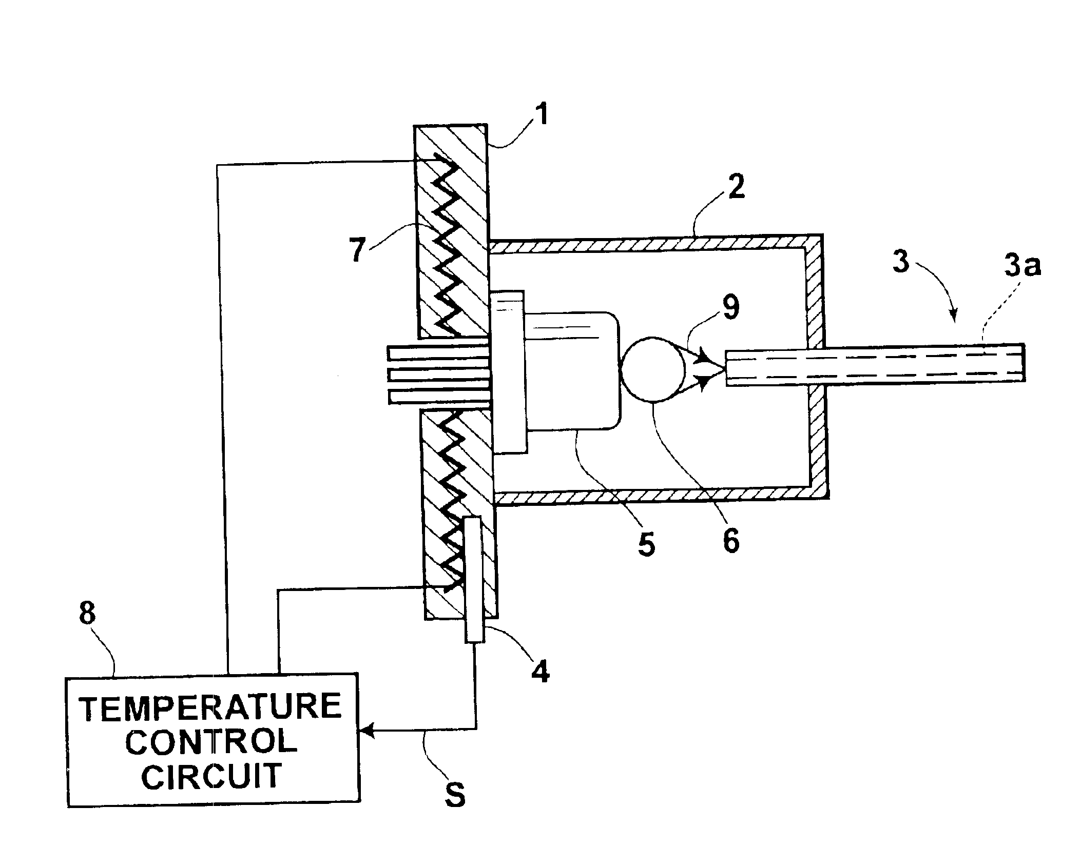
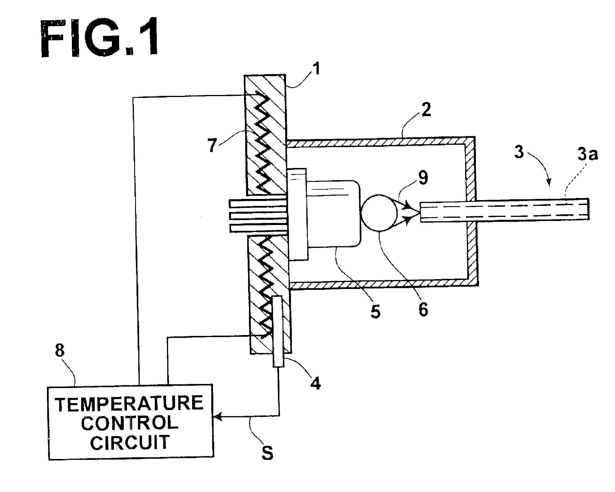
FIG. 1 is a partially cutaway side view showing the transmission apparatus using a plastic fiber in accordance with the present invention. The section illustrated in FIG. 1 constitutes a light sending module section. As illustrated in FIG. 1, the transmission apparatus comprises abase plate 1. The transmission apparatus also comprises a can type package 2, which is secured to the base plate 1. The transmission apparatus further comprises a plastic fiber 3, whose one end is inserted into the can type package 2. The transmission apparatus still further comprises a thermistor 4, which is located within a hole made through the base plate 1. The transmission apparatus also comprises an end face emission type of semiconductor laser 5, which is accommodated within the can type package 2 and has a stem fitted to the base plate 1. The transmission apparatus further comprises a ball lens 6, which is accommodated within the can type package 2. An electric heater 7 is built in the base plate 1....

second embodiment

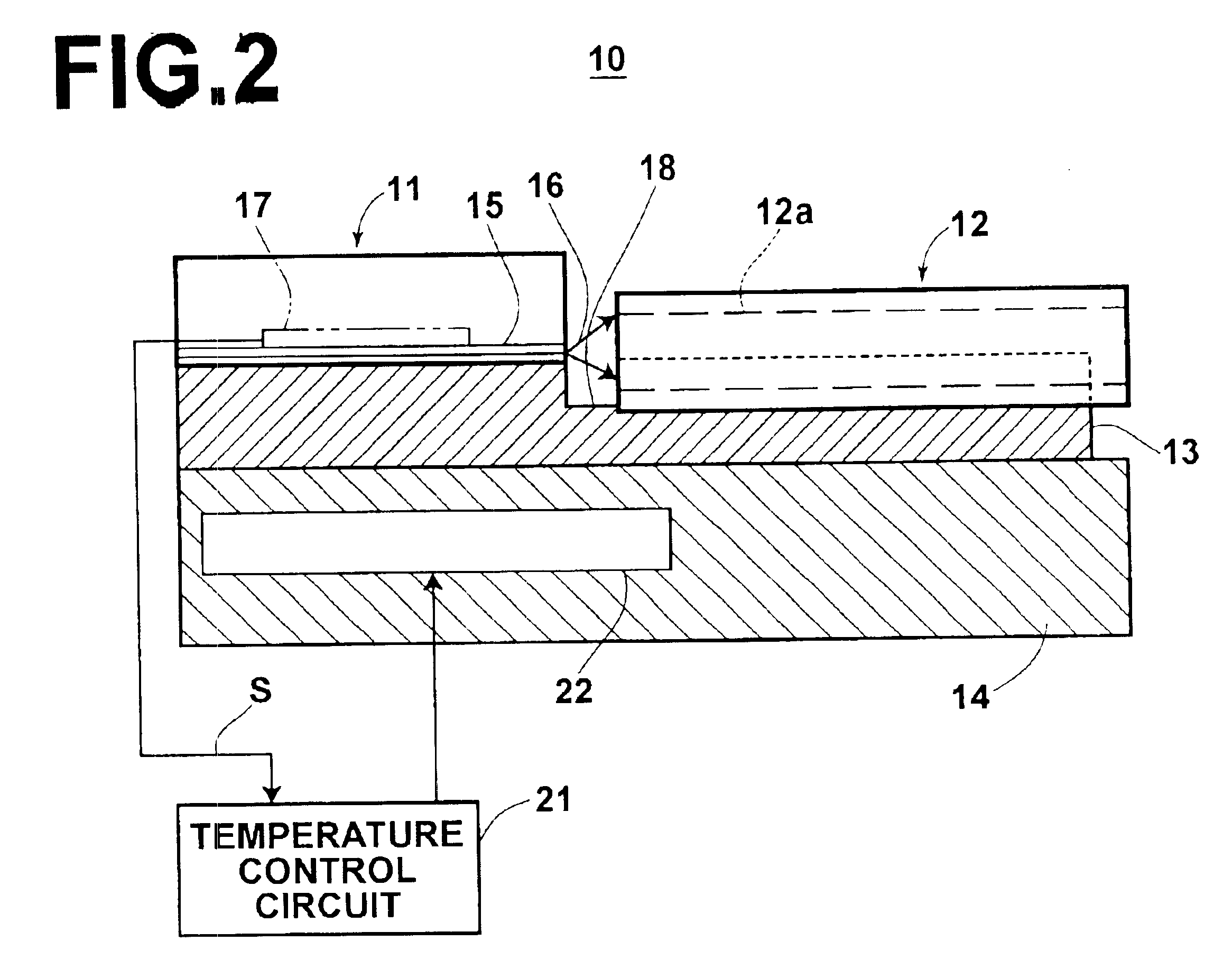
A second embodiment of the transmission apparatus using a plastic fiber in accordance with the present invention will be described hereinbelow. FIG. 2 is a side view showing a second embodiment of the transmission apparatus using a plastic fiber in accordance with the present invention. FIG. 3 is a plan view showing part of the transmission apparatus of FIG. 2, which part is located above a submount of the transmission apparatus. FIG. 4 is a front view showing part of the transmission apparatus of FIG. 2, which part is located above a submount of the transmission apparatus. the transmission apparatus using a plastic fiber in accordance with the present invention constitutes a sending submodule 10, which is employed in a sending-receiving module 30 illustrated in FIG. 5 as will be described later. As illustrated in FIG. 2, the sending submodule 10 comprises a semiconductor laser chip 11, which is of the end face emission type. The sending submodule 10 also comprises a PMMA plastic fi...


PUM


Abstract

Light, which has been produced by a semiconductor device and has wavelengths falling within the range of 630 nm to 680 nm, is propagated through a plastic fiber provided with a core containing a polymethyl methacrylate as a principal constituent. The temperature of the semiconductor device is adjusted by a temperature adjusting system comprising a heater for heating the semiconductor device, a temperature detector for detecting the temperature of the semiconductor device and feeding out a temperature detection signal, and a control circuit for controlling actuation of the heater in accordance with the temperature detection signal in order to set the temperature of the semiconductor device at a predetermined target value that is lower than the highest temperature assumed to occur under an environment, in which the semiconductor device is located.

Description

BACKGROUND OF THE INVENTION1. Field of the InventionThis invention relates to a transmission apparatus, which utilizes a plastic fiber, for use in an optical communication system, and the like.2. Description of the Related ArtOrdinarily, as light propagation paths in optical communication, single mode fibers or multi-mode fibers containing quartz glass as a principal material are utilized. The single mode fibers or the multi-mode fibers containing quartz glass as a principal material have a diameter of at most 200 μm. In alignment processes for the fibers, a high position matching accuracy on the order of micron is required. Therefore, fiber laying operations under ordinary environmental conditions, such as conditions at construction work sites, are not easy to perform. The difficulty of the fiber laying operations obstructs further popularization of the fibers described above.Recently, plastic fibers, which have a comparatively large diameter and are comparatively easy to lay, have...

Claims


Application Information

Patent Timeline
Patent Type & Authority Patents(United States)
IPC IPC(8): B41J2/46B41J2/447G02B6/42H01S5/06H01S5/00H01S5/068B41J2/44B41J2/45B41J2/455G02B6/02H01L33/48H01S5/022
CPCB41J2/46G02B6/4201G02B6/02G02B6/4246H01S5/06804H01S5/02284H01S5/02453H01S5/0612H01S5/0224G02B6/4271H01S5/02251H01S5/0234G02B6/43
Inventor HAYAKAWA, TOSHIRO
Owner FUJIFILM CORP
Why Eureka
Try Eureka