Low-profile low-rcs ultra-wide bandwidth angular scanning strong mutual coupling phased array antenna based on polarization conversion materials

A phased array antenna and polarization conversion technology, which is applied to antenna combinations, antennas, antenna arrays and other directions with different interactions, can solve problems such as being in the blank stage, and achieve the goals of reducing self-weight, improving performance, and stabilizing impedance transformation characteristics Effect

Active Publication Date: 2019-08-30
UNIV OF ELECTRONICS SCI & TECH OF CHINA
View PDF7 Cites 0 Cited by
  • Summary
  • Abstract
  • Description
  • Claims
  • Application Information

AI Technical Summary

Problems solved by technology

On the one hand, in order to achieve ultra-wide bandwidth angular scanning, the height of the antenna profile of the strong mutual coupling antenna is strictly restricted, and realizing the low profile of the antenna is one of the difficulties of this type of array antenna; The research on the scattering characteristics of this new type of broadband phased array antenna with strong mutual coupling effect is still very little, and it is basically in its infancy, and the low RCS design for this type of array antenna is still in the blank stage

Method used


Image

  • Low-profile low-rcs ultra-wide bandwidth angular scanning strong mutual coupling phased array antenna based on polarization conversion materials
  • Low-profile low-rcs ultra-wide bandwidth angular scanning strong mutual coupling phased array antenna based on polarization conversion materials
  • Low-profile low-rcs ultra-wide bandwidth angular scanning strong mutual coupling phased array antenna based on polarization conversion materials

Examples


Embodiment 1

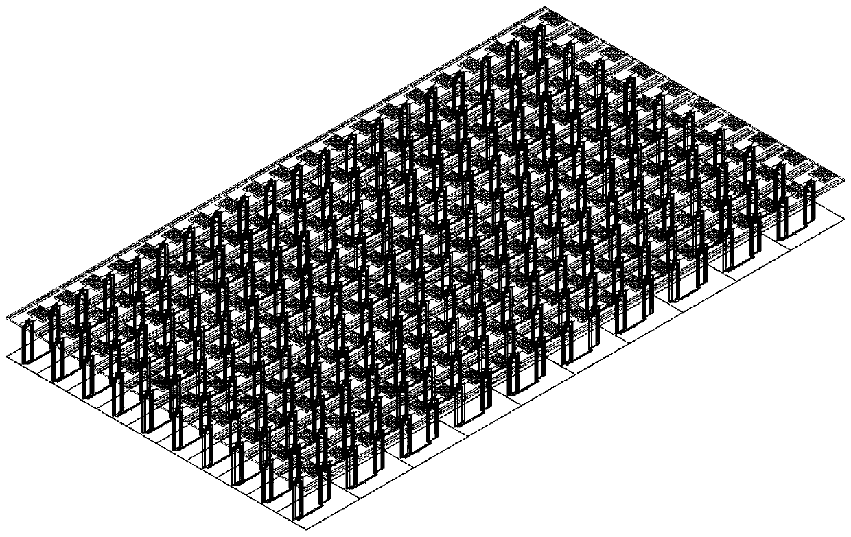
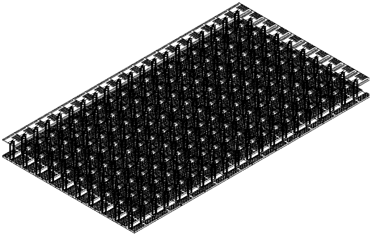
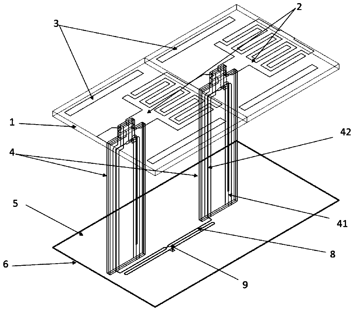
[0031] Reference figure 1 with figure 2 Both of the two array antennas of this embodiment are composed of a periodic structure of antenna sub-array elements printed with closely arranged dipole elements. The structure includes a dielectric substrate 1; an interdigital dipole unit 2 printed on the dielectric substrate 1; rectangular patches 3 printed on both sides of the dipole unit 2; stripline baluns located under the dielectric substrate 1 4; The first dielectric layer 6 located below the strip line balun 4 and the upper surface is the metal floor layer 5; the one-to-two power dividing network 8 printed on the lower surface of the first dielectric layer 6; to the one-to-two power dividing network 8. Microwave coaxial cable for feeder 9. The only difference in structure is figure 2 The antenna structure shown also includes a polarization conversion material 7 loaded on the metal floor layer 5 above the first dielectric layer 6. The height of the entire antenna is only 0.267...


PUM


Abstract

The invention discloses a low-profile low-RCS ultra-wide bandwidth angular scanning strong mutual coupling phased array antenna based on polarization conversion materials. The antenna can realize two-dimensional wide-angle scanning under four octaves, and its profile height is only 0.267 times the high-frequency wavelength, which meets the low-profile requirements of the antenna. At the same time, the new polarization conversion material loaded effectively reduces the RCS of the antenna itself without affecting the radiation performance of the antenna itself. The entire antenna structure mainly includes: a dielectric substrate (1); an interdigitated dipole unit (2) printed on the dielectric substrate; rectangular patches (3) on both sides of the dipole; the antenna is connected to the floor under the dielectric substrate. The stripline balun (4); the upper surface below the balun is the dielectric layer (6) of the metal floor layer (5); the polarization conversion material (7) loaded on the metal floor; the centimeter network on the lower surface of the dielectric layer (8); the microwave coaxial cable (9) feeding the centimeter network.

Description

Technical field [0001] The invention belongs to the technical field of antenna engineering, and particularly relates to an ultra-wide bandwidth dimensional scanning phased antenna array system. Specifically, it is based on a strong mutual coupling effect and loaded with a new polarization conversion metamaterial (PCM), At the same time, it has the characteristics of low profile and low RCS, and can realize the phased antenna array of ultra-wide bandwidth angular scanning. It is suitable for platforms that require good antenna stealth performance and low profile characteristics, and can realize ultra-wide bandwidth angular scanning. Background technique [0002] Stealth technology, as an important part of the modern military field, is also an important research direction in the current antenna technology field. Radar Cross Section (RCS), abbreviated as RCS, is a measure of the scattering power of a target in a given direction under plane wave illumination, and is an important indi...

Claims


Application Information

Patent Timeline
Patent Type & Authority Patents(China)
IPC IPC(8): H01Q21/00H01Q21/29H01Q15/24
Inventor 杨仕文鲍鸿飞陈益凯肖乾树肖仕伟屈世伟
Owner UNIV OF ELECTRONICS SCI & TECH OF CHINA
Why Eureka
Try Eureka