Receiving end high-order LC compensation magnetic resonance wireless power transmission system

A wireless power transmission and receiving end technology, applied in control/regulation systems, high-efficiency power electronic conversion, electrical components, etc., can solve the problems of poor system transmission stability, low system transmission efficiency, inability to apply variable load charging mode, etc. Efficiency smoothness, high efficiency effect

Pending Publication Date: 2022-05-27
GUANGDONG UNIV OF TECH
View PDF0 Cites 0 Cited by
  • Summary
  • Abstract
  • Description
  • Claims
  • Application Information

AI Technical Summary

Problems solved by technology

[0003] An LCC-S type wireless power transmission system and parameter design method in the prior art, the system transmission efficiency is relatively low under light load conditions, and the system transmission stability is poor. As the load increases, the system transmission efficiency drops rapidly. When using wireless power transfer to charge the battery, it cannot be applied to the variable load charging mode during the battery charging process

Method used


Image

  • Receiving end high-order LC compensation magnetic resonance wireless power transmission system
  • Receiving end high-order LC compensation magnetic resonance wireless power transmission system
  • Receiving end high-order LC compensation magnetic resonance wireless power transmission system

Examples


Embodiment 1

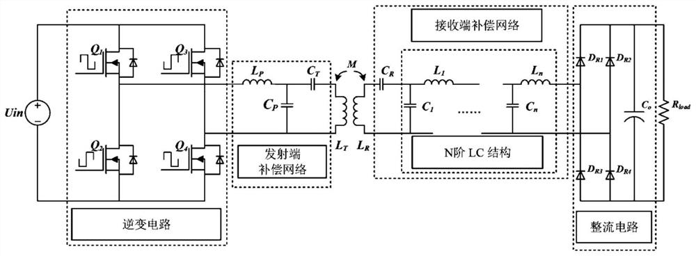
[0049] A magnetic resonance wireless power transmission system with high-order LC compensation at the receiving end, such as figure 1 shown, including: transmitter and receiver;

[0050] The transmitting end includes a transmitting end compensation network and a transmitting coil L T , the transmitter compensation network is connected to the transmitter coil L T , the AC signal is input to the transmitter compensation network, the transmitter compensation network converts the input electrical energy into high-frequency voltage and current signals, and the high-frequency voltage and current signals are input to the transmitter coil L T , the transmitter coil L T Sending electric energy, the current in the transmitting coil presents a constant current characteristic through the transmitting end compensation network, and the transmitting coil transmits the electric energy to the receiving coil through magnetic coupling;

[0051] The receiving end includes a receiving coil L R...

Embodiment 2

[0054] On the basis of Example 1, as figure 1 As shown, the transmitter compensation network in this embodiment is an LCC series-parallel resonant network, and the transmitter also includes an inverter circuit. The input end of the inverter circuit is connected to the DC power supply, and the output end of the inverter circuit is connected to the transmitter compensation network. The inverter circuit Convert DC input to AC signal output. The inverter circuit is a full-bridge inverter circuit, and the inverter circuit includes a MOS transistor Q 1 , MOS transistor Q 2 , MOS transistor Q 3 and MOS transistor Q 4 ;MOS transistor Q 1 the drain and MOS transistor Q 3 The drain connection of the MOS transistor Q 2 The source and MOS transistor Q 4 The source is connected, MOS transistor Q 1 The source is connected to the MOS transistor Q 2 drain, MOS transistor Q 3 The source is connected to the MOS transistor Q 4 drain, MOS transistor Q 3 the drain and MOS transistor Q ...

Embodiment 3

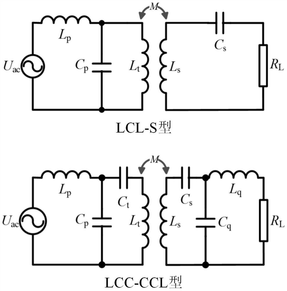
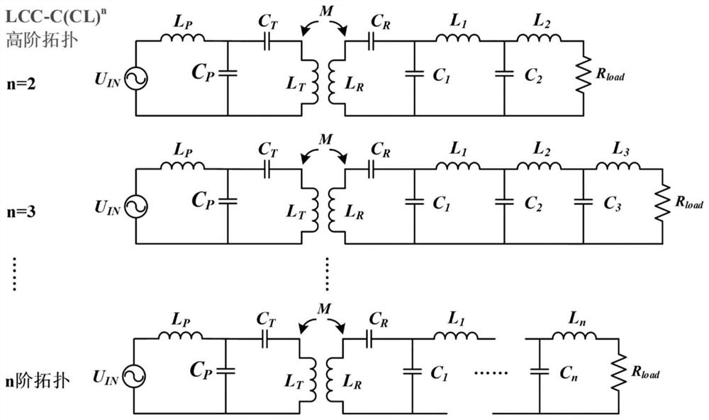
[0058]In the wireless power transmission system, in order to realize the same frequency resonance of the inductance of the receiving coil and the transmitting coil and improve the power and efficiency of the system energy transmission, it is necessary to compensate the transceiver coil at the same time by adding a compensation network to the transceiver mechanism. The compensation network plays a vital role in the magnetic resonance coupled wireless charging system. The configuration of the bilateral compensation network parameters of the transceiver mechanism can change the equivalent impedance characteristics of the system, thereby minimizing the reactive power of the system and improving the The overall power factor of the system and increase the coupling between the transceiver coils. There are four basic topological structures S-S, S-P, P-P, and P-S in the compensation network according to the difference in the series-parallel combination of the bilateral compensation netw...


PUM


Abstract

The invention provides a receiving end high-order LC compensation magnetic resonance wireless power transmission system, and relates to the technical field of wireless power transmission. Comprising a transmitting end and a receiving end; the transmitting end comprises a transmitting end compensation network and a transmitting coil, the transmitting end compensation network is connected with the transmitting coil, an alternating current signal is input into the transmitting end compensation network, the current in the transmitting coil presents a constant current characteristic through the transmitting end compensation network, and the transmitting coil transmits electric energy to the receiving coil through magnetic coupling; the receiving end comprises a receiving coil and a receiving end compensation network; the receiving end compensation network comprises a high-order LC structure with a plurality of orders of LC; the receiving coil is connected with the receiving end compensation network and receives the electric energy emitted by the transmitting coil, and the transmission efficiency is stabilized through the receiving end compensation network. When the load changes, the LCC-C (LC) n high-order topology family has higher efficiency stability compared with the traditional topology.

Description

technical field [0001] The present invention relates to the technical field of wireless power transmission, and more particularly, to a magnetic resonance wireless power transmission system with high-order LC compensation at the receiving end. Background technique [0002] Compared with wired power transmission, wireless power transmission technology has the advantages of stability, safety, avoiding port aging and wear, reducing the risk of arc and leakage, and being less affected by harsh environments such as wet dust. Generally, in wireless power transmission systems, in order to realize the transceiver coil Inductor resonance at the same frequency and improving system energy transmission power and efficiency require simultaneous compensation of the transceiver coil by adding a compensation network to the transceiver circuit. The compensation network plays a vital role in the magnetic resonance coupled wireless power transmission system. The configuration of the bilateral ...

Claims


Application Information

Patent Timeline
IPC IPC(8): H02J50/12H02M3/335H02M1/088
CPCH02J50/12H02M3/3353H02M1/088Y02B70/10
Inventor 李志忠龙淑群张亦弛邱炜夏振林
Owner GUANGDONG UNIV OF TECH
Why Eureka
Try Eureka