Method for controlling a multi-engine bay, control system for a multi-engine bay and multi-engine bay

a control system and multi-engine technology, applied in the direction of rocket engine plants, machines/engines, cosmonautic vehicles, etc., can solve the problems of increasing the damage rate of the turbomachine, increasing the vibratory energy of the turbomachine, and increasing the risk of the engine failing, so as to reduce the damage rate, reduce the torque applied thereto, and reduce the damage rate

Pending Publication Date: 2021-04-15
ARIANEGRP SAS
View PDF4 Cites 0 Cited by
  • Summary
  • Abstract
  • Description
  • Claims
  • Application Information

AI Technical Summary

Benefits of technology

[0039]Consequently, in accordance with the invention, modifying the operating limits of an engine in a multi-engine bay and having a damaged valve by reducing the maximum value of the position-holding current of the valve leads to controlling the bay in a manner that usually requires the position-holding current of the valve to be reduced, and thus requires the torque that is applied thereto being reduced; this leads to reducing the rate of damage of the engine of which the valve forms a part.
[0040]Finally, in a combustion chamber, it is possible to reduce the maximum value of the mixture ratio that is acceptable in the chamber in order to reduce the rate of damage to the chamber, and consequently to the engine of which the chamber forms a part.

Problems solved by technology

As a result of this degradation, the risk of an engine failing, and consequently of the bay failing, increases progressively during its stages of operation.
Increasing the power delivered by the pump, or the speed of rotation of the turbomachine, leads to increasing the vibratory energy of the turbomachine, and thus to increasing its rate of damage.

Method used


Image

  • Method for controlling a multi-engine bay, control system for a multi-engine bay and multi-engine bay
  • Method for controlling a multi-engine bay, control system for a multi-engine bay and multi-engine bay
  • Method for controlling a multi-engine bay, control system for a multi-engine bay and multi-engine bay

Examples


Embodiment Construction

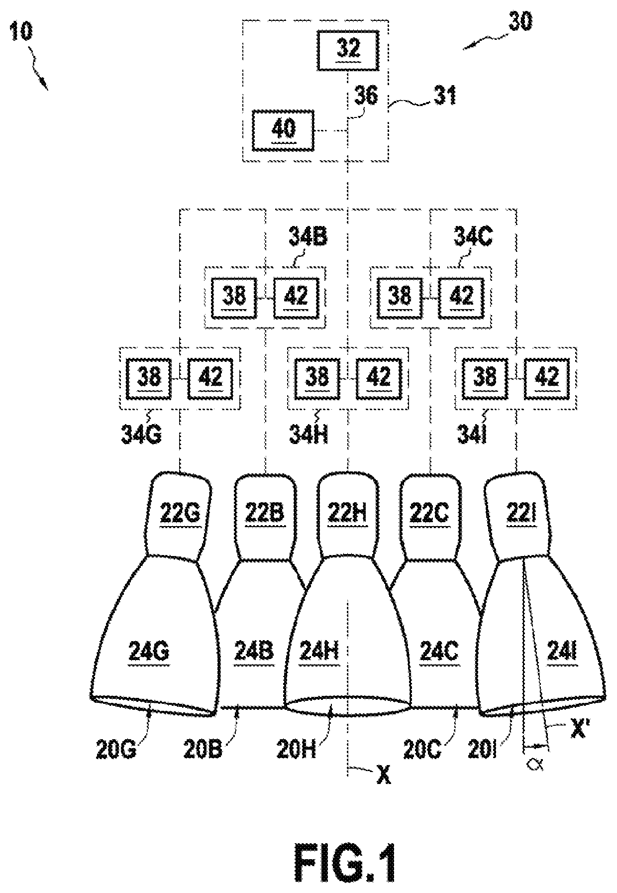
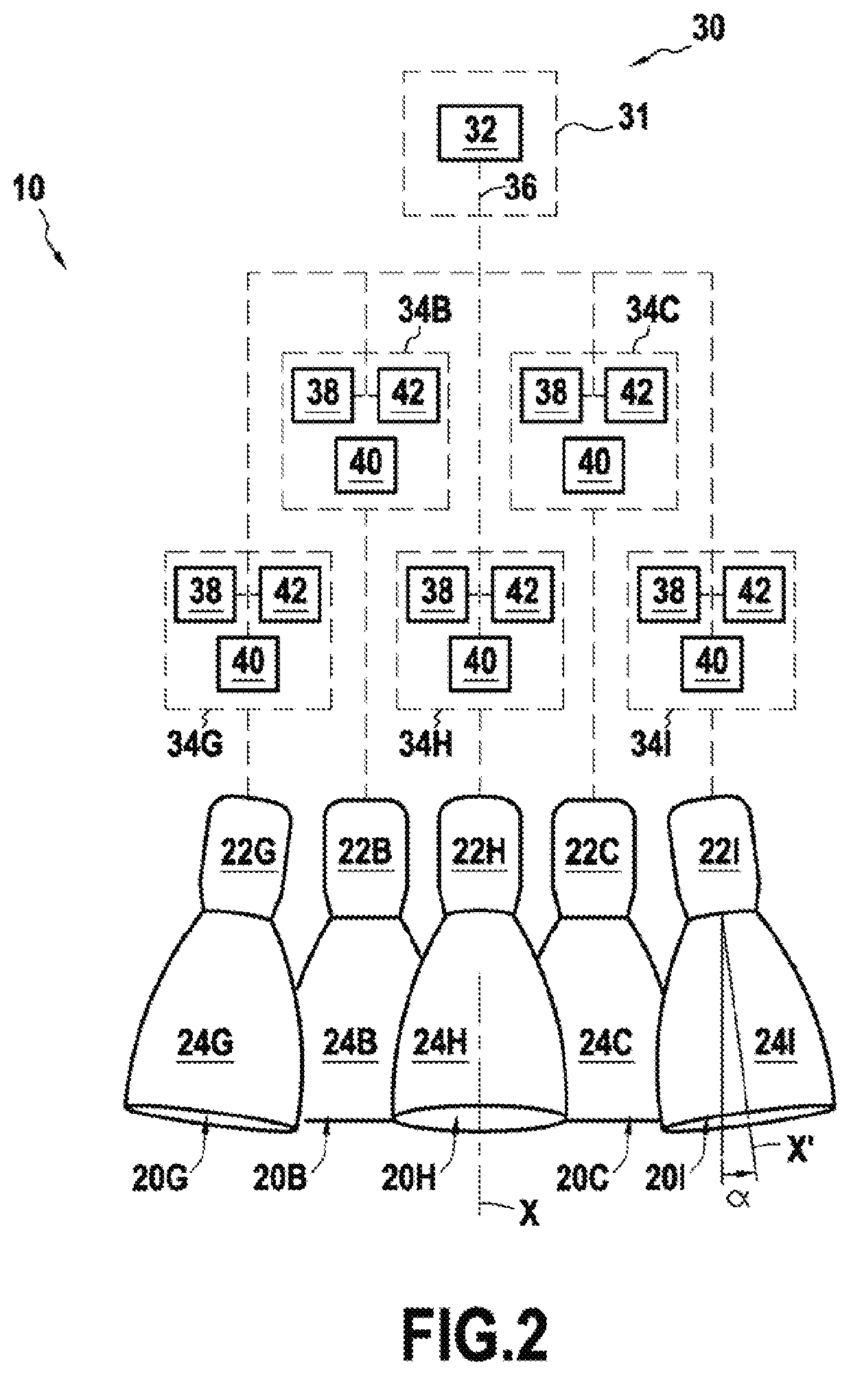
[0070]A multi-engine bay 10 is described below in two slightly differing embodiments, with reference respectively to FIG. 1 and to FIG. 2.

[0071]In both embodiments, the multi-engine bay 10 comprises 10 engines respectively referenced 20A, 20B, . . . , 20J and referenced collectively as engines 20 (only five engines are shown in FIG. 1).

[0072]The bay also has two propellant tanks, circuits for distributing and pressurizing the propellants, and various additional pieces of equipment (not shown).

[0073]Each of these engines is a rocket engine comprising a combustion chamber (chambers 22A, 22B, . . . , 22J) each arranged upstream from a nozzle (nozzles 24A, 24B, . . . , 24J). The references 22 and 24 are used respectively to designate collectively the combustion chambers and the nozzles.

[0074]The bay 10 is controlled by a control system 30.

[0075]The control system 30 comprises a central computer 31 and ten engine computers 34A, 34B, . . . , 34J.

[0076]The engine computers 34A, 34B, . . . ...


PUM


Abstract

A method of controlling a multi-engine bay in which the following steps are performed: a) controlling the bay so that it delivers desired thrust and each engine is operated in compliance with a set of operating limits for the engine; b) periodically evaluating a level of damage for each of the engines, the level of damage of an engine being information representative of a probability of the engine failing; c) for each engine, periodically evaluating whether its level of damage exceeds a predetermined value; and d) if the level of damage of an engine, referred to as a “damaged” engine, exceeds a predetermined value, modifying at least one operating limit of the damaged engine so that the rate of damage of the damaged engine is less than a predetermined maximum rate of engine damage.

Description

FIELD OF THE INVENTION[0001]The invention relates to controlling engines in a multi-engine bay, and to monitoring their states. A multi-engine bay is defined herein as being a propulsion assembly comprising a plurality of engines arranged in such a manner as to be capable of generating forces that add together. More particularly, the invention applies to a situation in which the engines are reaction engines, and where the bay is thus constituted by a plurality of rocket engines.BACKGROUND OF THE INVENTION[0002]In a multi-engine bay, the state of each of the engines degrades progressively as a function of the length of time the engine has been in use and of the stresses to which it has been subjected in operation. As a result of this degradation, the risk of an engine failing, and consequently of the bay failing, increases progressively during its stages of operation.[0003]A first object of the invention is thus to propose a method of controlling a multi-engine bay that enables the r...

Claims


Application Information

Patent Timeline
Patent Type & Authority Applications(United States)
IPC IPC(8): B64G1/40F02K9/80
CPCB64G1/40F02K9/80B64D31/12F02K9/00F05D2260/80B64G1/401B64G1/402
Inventor LE GONIDEC, SERGEKLEIN, MANUEL SYLVAIN FRANÇOIS
Owner ARIANEGRP SAS
Why Eureka
Try Eureka