Insulated plug with RFID tag

a technology of insulated plugs and tags, which is applied in the direction of loop antennas, radiating element structural forms, instruments, etc., can solve the problems of difficult reading and use, difficult placement of existing insulation plugs therein or difficult to achieve temperature monitoring of the connector inside the t-type cable connector, etc., to increase the recognition distance, increase the gain of the tag antenna, and increase the recognition distance

Active Publication Date: 2018-09-20
ZHEJIANG JOHAR TECH CO LTD
View PDF0 Cites 4 Cited by
  • Summary
  • Abstract
  • Description
  • Claims
  • Application Information

AI Technical Summary

Benefits of technology

[0014]To sum up, in the insulated plug with the RFID tag provided in this embodiment, by disposing the installation hole corresponding to the conductive rod at the substrate of the tag antenna, the RFID tag is fixed inside the main body of the insulated plug through the installation hole. When the tag chip on the RFID tag is set to be a chip with a function of testing temperature, an external reading and writing device can monitor an internal temperature of the insulated plug by reading the RFID tag. In addition, in the tag antenna, by forming the radiation part and the reflection part at both ends of the substrate and setting the reflection part to be closed, the energy radiated from the radiation part is superimposed after being reflected by the reflection part so as to increase the gain of the tag antenna and greatly increase the recognition distance of the tag antenna. And when the RFID tag antenna is attached to a metal (a fixing piece such as a nut), the reflection part can shield the effect of the metal located at the side of the reflection part so as to increase the recognition distance and achieve an anti-metal effect.
[0015]Further, by setting the widths and the circumferences of the radiation part and the reflection part to match the impedance of the tag chip connected with the feeding part, the transmission coefficient of the antenna is increased, thereby increasing the recognition distance of the tag antenna. Further, the gain of the antenna can be increased by increasing the thickness of the substrate such that the energy reflected by the reflection part and the energy radiated by the radiation part can be further superposed remotely to obtain a longer recognition distance. By installing the installation hole at the substrate, the conductive rod in the insulated plug can pass through the installation hole and be fixedly connected with the tag, thereby solving the installation problem of the tag in the insulated plug. The tag antenna has a simple structure and is particularly suitable for mass production.

Problems solved by technology

In a power ring grid cabinet, a working voltage is often above 10 KV, key nodes in a cable often have heating phenomenon with a high temperature, and these nodes are always important hidden danger points in power accidents.
However, the metal structure has a reflection effect on the energy of the antenna, and the cylindrical space of the T-shaped cable connector is narrow, which makes the existing temperature-measuring tag difficult to be placed therein or difficult to read and use.
Therefore, the existing insulation plug is very difficult to achieve temperature monitoring of the connector inside the T-type cable connector.

Method used


Image

  • Insulated plug with RFID tag
  • Insulated plug with RFID tag
  • Insulated plug with RFID tag

Examples


Embodiment Construction

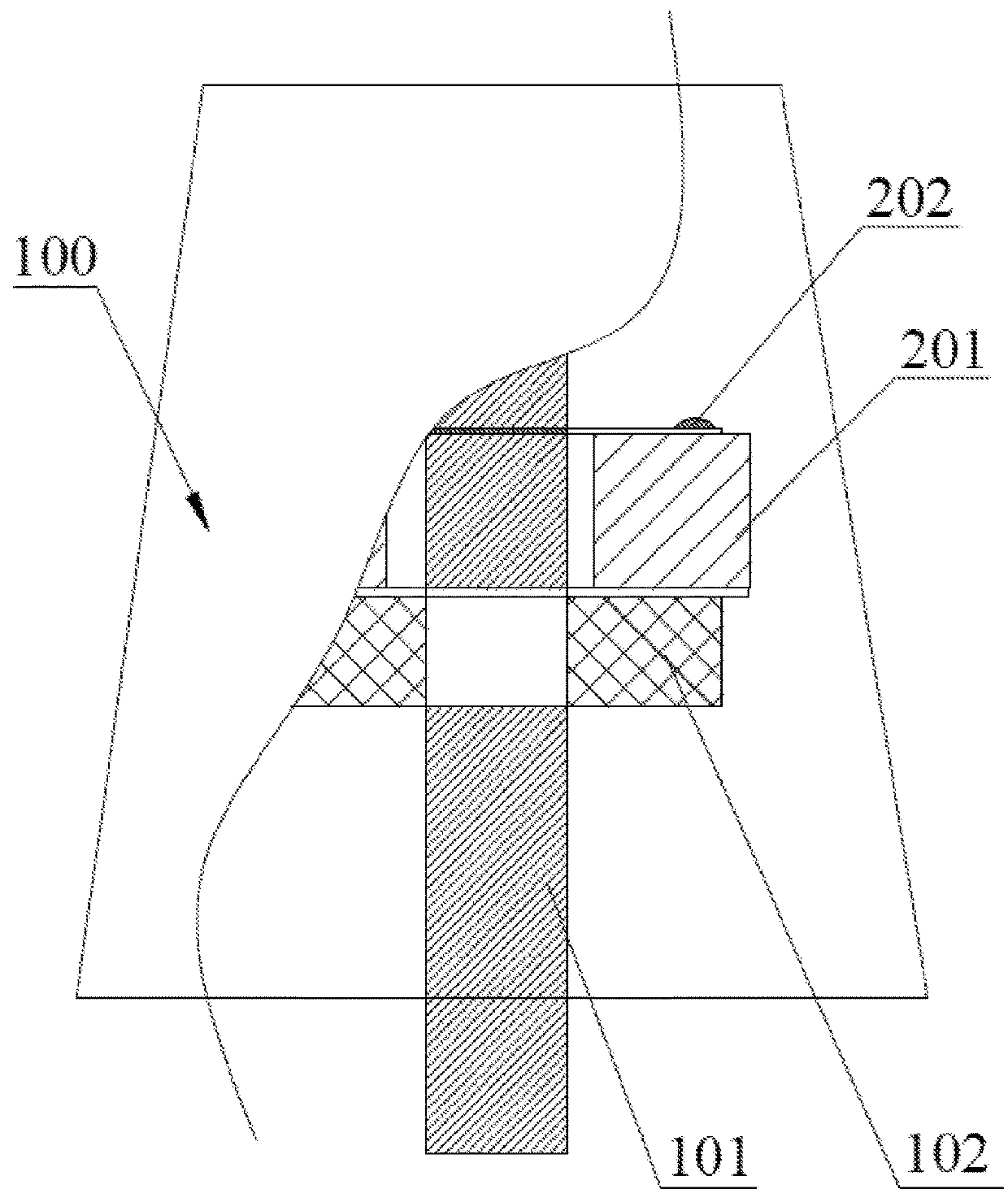
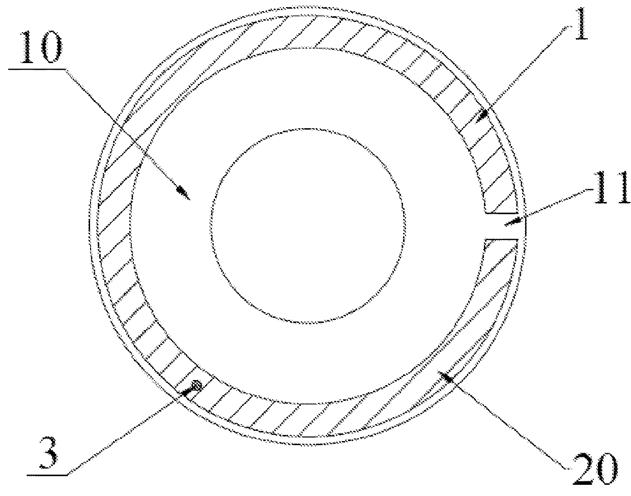
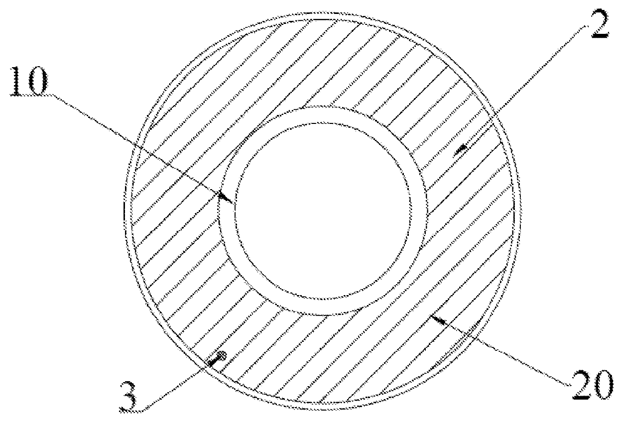
[0025]As shown in FIG. 1 to FIG. 5, this embodiment provides an insulated plug with an RFID tag including a main body 100 and an RFID tag 200. The main body 100 includes a conductive rod 101 and a fixing piece 102. The RFID tag 200 includes a tag antenna 201 and a tag chip 202 connected with a feeding part of the tag antenna 201. The tag antenna 201 includes a substrate 10 and an antenna structure 20. The substrate 10 has an installation hole, and the conductive rod 101 passes through the installation hole and is fixed with the installation hole. The antenna structure 20 is disposed at the substrate 10, and the antenna structure 20 includes a radiation part 1, a reflection part 2 and a connection part 3. The radiation part 1 is formed at one end of the substrate 10, and the radiation part 1 has a feeding part 11. The reflection part 2 is formed at the other end of the substrate 10 and is closed, and the reflection part 2 reflects energy radiated from the radiation part 1. The connec...


PUM


Abstract

This invention provides an insulated plug with an RFID tag including a main body and the RFID tag. The main body includes a conductive rod. The RFID tag includes a tag antenna and a tag chip connected at a feeding part of the tag antenna. The tag antenna includes a substrate and an antenna structure. The substrate has an installation hole, and the conductive rod passes through the installation hole and is fixed with the installation hole. The antenna structure is disposed at the substrate and includes a radiation part, a reflection part and a connection part. The radiation part is formed at one end of the substrate and has a feeding part. The reflection part is formed at the other end of the substrate and is closed. The connection part is disposed at the substrate and is electrically connected with the radiation part and the reflection part.

Description

CROSS-REFERENCE TO RELATED APPLICATIONS[0001]This Non-provisional application claims priority under 35 U.S.C. § 119(a) on Patent Application No(s). 201710153031.4 filed in People's Republic of China on Mar. 15, 2017, the entire contents of which are hereby incorporated by reference.BACKGROUND OF THE INVENTIONField of the Invention[0002]This invention relates to a technical field of radio frequency identification, and more particularly, to an insulated plug with an RFID tag.Description of the Related Art[0003]At present, passive UHF RFID technology has been widely used in various industries. A passive UHF RFID sensor chip developed according to the RFID technology combined with a sensor technology has made the UHF RFID technology more widely and deeply applied in the fields of electric power and other industries. In a power ring grid cabinet, a working voltage is often above 10 KV, key nodes in a cable often have heating phenomenon with a high temperature, and these nodes are always ...

Claims


Application Information

Patent Timeline
Patent Type & Authority Applications(United States)
IPC IPC(8): G06K19/077G06K19/07H01Q1/38H01Q15/14H01Q13/10
CPCG06K19/07749G06K19/0723H01Q1/38H01Q15/14H01Q13/10H01Q1/12H01Q1/2225H01Q1/36H01Q19/10H01Q23/00H01Q1/44H01Q7/00H01Q9/265
Inventor JI, HONGHONG
Owner ZHEJIANG JOHAR TECH CO LTD
Why Eureka
Try Eureka