Metalized fabric heating blanket and method of manufacturing such

a technology of metalized fabric and heating blanket, which is applied in the field of heating blankets, can solve the problems of not being metalized fabrics are usually stiff and not soft to the touch, and metalized fabrics are usually not ideal for such a task

Active Publication Date: 2018-09-20
ENCOMPASS GROUP
View PDF14 Cites 3 Cited by
  • Summary
  • Abstract
  • Description
  • Claims
  • Application Information

AI Technical Summary

Benefits of technology

[0007]In a preferred form of the invention a heating blanket comprises a carbon veil material, a first electrically conductive strip electrically coupled along a first side of the carbon veil, a second electrically conductive strip electrically coupled along a second side of the carbon veil material opposite the first side of the carbon veil material, a first electrically insulative layer overlaying a first surface of the carbon veil material, a second electrically insulative layer overlaying a second surface of the carbon veil material oppositely disposed from the first surface of the carbon veil material, and an electrical control circuit electrically coupled to the first electrically conductive strip and the second electrically conductive strip. With this construction, current passing from the electrical control circuit to the first and second electrically conductive strips passes through the carbon veil to create heat.

Problems solved by technology

These materials have provided a certain amount of heat retaining qualities, however, they are not optimal for such a task.
These metalized fabrics however are usually stiff and not soft to the touch.

Method used


Image

  • Metalized fabric heating blanket and method of manufacturing such
  • Metalized fabric heating blanket and method of manufacturing such
  • Metalized fabric heating blanket and method of manufacturing such

Examples


Embodiment Construction

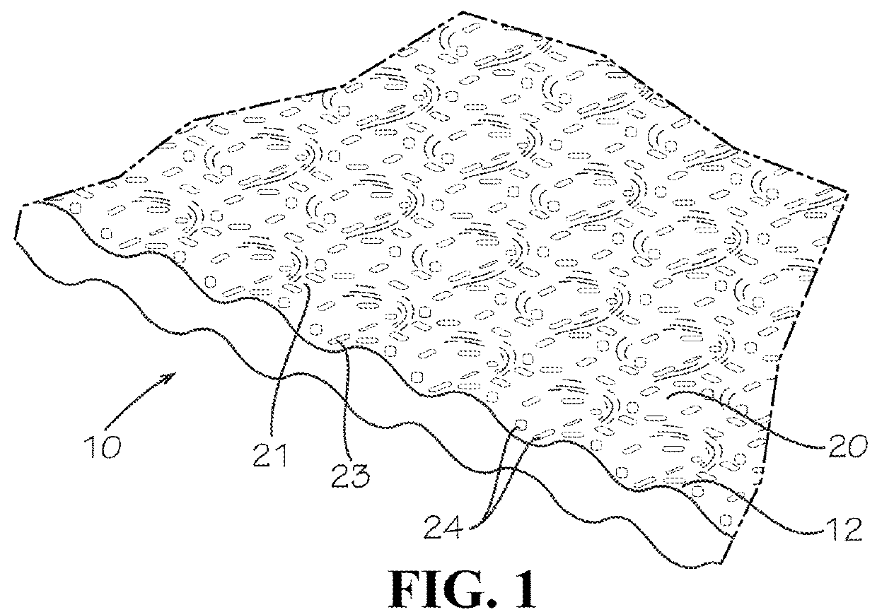
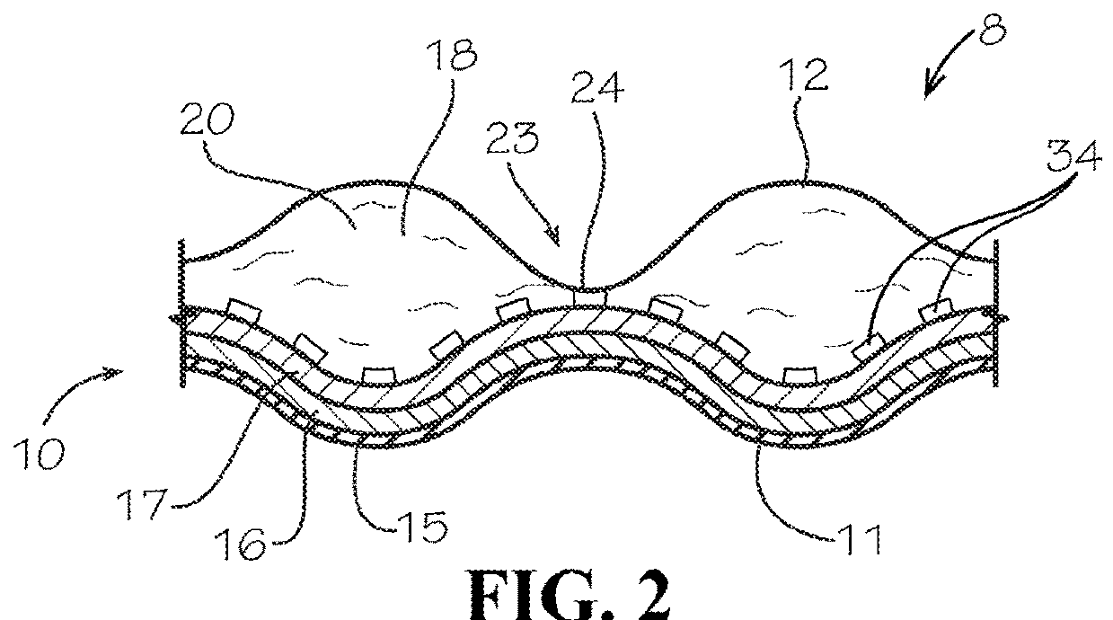
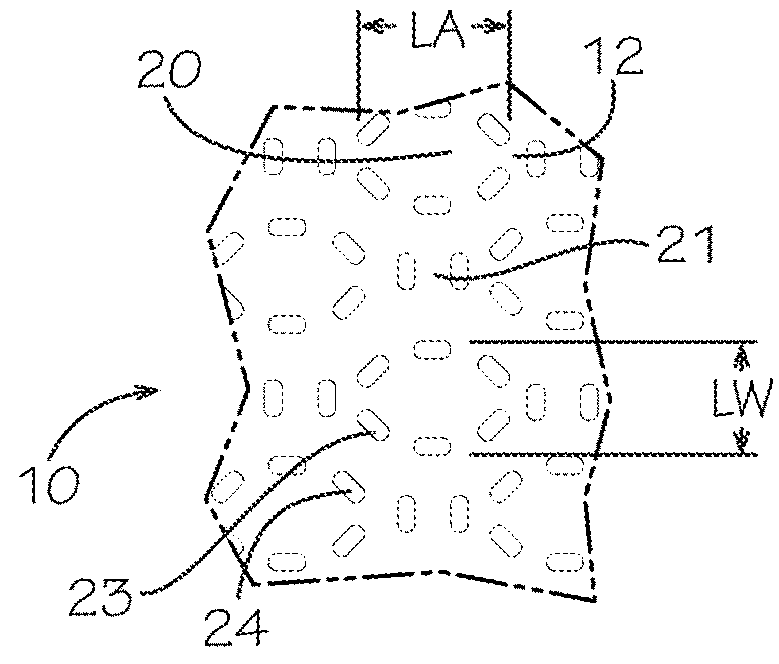
[0016]With reference next to the drawings, there is shown a warming blanket 8 made in part with a metalized fabric 10 embodying principles of the invention in a preferred form. The warming blanket 8 has a lower surface 11 which is intended to face away from a person (patient) overlaid with or donning the material and an upper surface 12 which is intended to face the person (patient). The metalized fabric includes a first layer 15 of clear thermoplastic (for example a polyethylene) material, a second layer 16 of vaporized aluminum material (metalized layer), a third layer 17 of thermoplastic (for example a polyethylene) material, and a fourth layer 18 of lofted billow spunbond thermoplastic (for example a polypropylene)non-woven material. The exterior surface of the first layer 15 constitutes the fabric lower surface 11, while the exterior surface of the fourth layer 18 constitutes the upper surface 12.

[0017]The warming blanket 8 also includes a resistive heating portion 30 positione...


PUM


Abstract

There is disclosed a warming blanket (8) having a metalized fabric exterior layer and a heating element formed from a random fiber carbon veil material (52). A conductive ink layer (56) is deposited onto opposite side edges of the carbon veil material as side rails. Lower conductive strips (58) are attached onto a bottom edge of the carbon veil material. Each lower conductive strip is electrically coupled to a side rail. The lower conductive strips have connecting ends (60) which are spaced from each other so as to accept a connection circuit board. Side conductive strips (62) are coupled to the conductive ink side rails. Electrical current controlled by the connection circuit board is passed through the carbon veil material to create heat.

Description

REFERENCE TO RELATED APPLICATION[0001]Applicant claims the benefit of U.S. Provisional Patent Application Ser. No. 62 / 471,103 filed Mar. 14, 2017 and entitled Metalized Fabric Heating Blanket.TECHNICAL FIELD[0002]This invention relates generally to heating blankets, and more particularly to heating blankets utilizing metalized fabrics and the method of manufacturing such and a method of manufacturing such.BACKGROUND OF THE INVENTION[0003]Insulative blankets and the like have been made for centuries. Such blankets have traditionally been made of a wool or cotton cloth. These materials have provided a certain amount of heat retaining qualities, however, they are not optimal for such a task.[0004]It has recently been discovered that blankets and clothing may be made of a metalized material to provide the added benefit of infrared heat reflecting capabilities to better prevent heat loss from a person. These products may be used as outdoor blankets, medical patient coverings, or other cl...

Claims


Application Information

Patent Timeline
Patent Type & Authority Applications(United States)
IPC IPC(8): H05B3/34H05B3/14
CPCH05B3/342H05B3/145H05B2203/016H05B2203/017H05B2203/002H05B2203/011H05B2203/034H05B2203/036A61F7/0097
Inventor HOWARD, ERIC JAMESTERRELL, KELLEYBERAN, MARK
Owner ENCOMPASS GROUP
Why Eureka
Try Eureka