
Eureka
For R&D, Eureka makes reading and utilizing patents & technical documents easy.
Eureka AIR
Designed for self-driven R&D workflows. Generate viable solutions, solve complex R&D challenges, empower your innovation with AI.

Eureka Materials
Designed for material experts only. Revolutionize your material R&D, from search, analyze, to developing new materials.

TechResearch
Generate reliable direction feasibility study reports for your R&D in just a few steps.

TechSeek
Discover and master advanced knowledge NOW. Basics, ideas, possibilities, all at once.

TechMind
As an expert in R&D Theories, TechMind can generates customized viable solutions instantly.

TechRisk
Analyze your overall solution with one click, know your potential R&D risks in advance.

TechMonitor
Get weekly tech updates, stay abreast of the latest tech innovations and key insights.
Ultrasound probe for a bore, equipped with an offcentring device
- Summary
- Abstract
- Description
- Claims
- Application Information
AI Technical Summary
Benefits of technology
Problems solved by technology
Method used
Image

Examples
Embodiment Construction
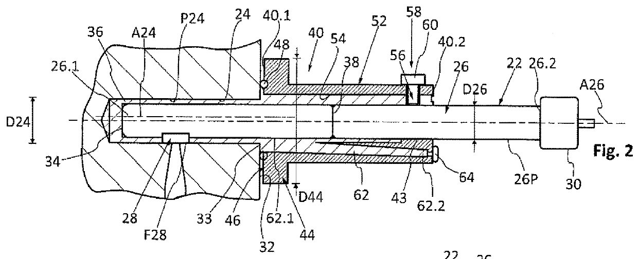
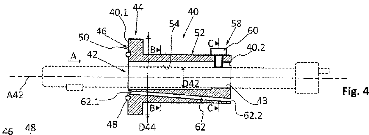
[0048]An ultrasound probe 22 for inspecting a bore 24 comprises:[0049]a body 26 which has a cylindrical side wall 26P, with an axis A26 and a substantially constant diameter D26, that extends from a first end 26.1 to a second end 26.2,[0050]an emission head 28 that protrudes relative to the cylindrical side wall 26P of the body 26 and is positioned in proximity to the first end 26.1, and[0051]a connection system 30 positioned at the second end 26.2.
[0052]For the rest of the description, a longitudinal direction is parallel to the axis A26 and a radial direction is perpendicular to the axis A26. A transverse plane is a plane perpendicular to the axis A26.
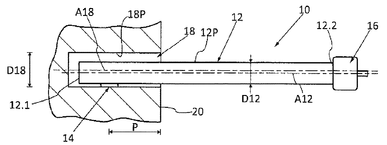
[0053]A bore is intended to mean a cylindrical hole, which may be blind, whatever its embodiment. The bore 24 comprises a cylindrical side wall P24, with an axis referenced A24 and a diameter D24. The bore 24 opens onto a planar peripheral surface 32 that extends over the perimeter of the bore 24. According to one configuration, the ...
PUM
 Abstract
Description
Claims
Application Information
 - R&D Engineer
- R&D Manager
- IP Professional
- Industry Leading Data Capabilities
- Powerful AI technology
- Patent DNA Extraction
Browse by: Latest US Patents, China's latest patents, Technical Efficacy Thesaurus, Application Domain, Technology Topic, Popular Technical Reports.
© 2024 PatSnap. All rights reserved.Legal|Privacy policy|Modern Slavery Act Transparency Statement|Sitemap|About US| Contact US: help@patsnap.com