
System and method of scanning an environment and generating two dimensional images of the environment

a technology of environment and system, applied in the direction of navigation instruments, distance measurement, instruments, etc., can solve the problems of requiring specialized personnel, and system complexity, and affecting the scanning process

Active Publication Date: 2018-10-04
FARO TECH INC
View PDF0 Cites 74 Cited by
  • Summary
  • Abstract
  • Description
  • Claims
  • Application Information

AI Technical Summary

Benefits of technology

The invention provides a system and method for generating a two-dimensional (2D) image of an environment using a 2D scanner and a 3D scanner. The 2D scanner is designed to be carried by a single person and has a light source, image sensor, and inertial measurement unit. The 2D scanner sweeps a beam of light in a horizontal plane to illuminate object points in the environment and collects 2D coordinates of points. The 3D scanner is also designed to be carried by a single person and has a light source, beam steering unit, and relative position indicator. The system can generate a 2D image of the environment based on the 2D scan data and the 3D coordinates of points collected during the scanning process. The technical effect of this invention is to provide a more efficient and accurate system for generating 2D and 3D images of an environment.

Problems solved by technology

These systems tend to be more complex and require specialized personnel to perform the scan.
Further, the scanning equipment including the movable structure may be bulky, which could further delay the scanning process in time sensitive situations, such as a crime or accident scene investigation.

Method used


Image

  • System and method of scanning an environment and generating two dimensional images of the environment
  • System and method of scanning an environment and generating two dimensional images of the environment
  • System and method of scanning an environment and generating two dimensional images of the environment

Examples


Embodiment Construction

[0036]The present invention relates to a device that includes a system having a 2D scanner that works cooperatively with an inertial measurement unit to generate an annotated two-dimensional map of an environment.

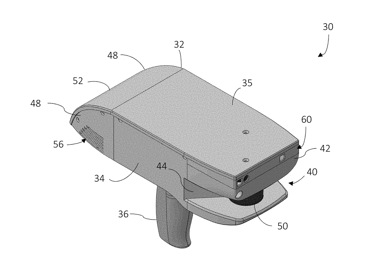
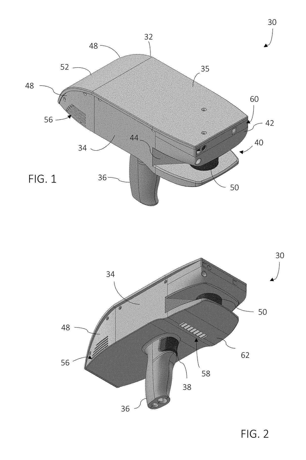
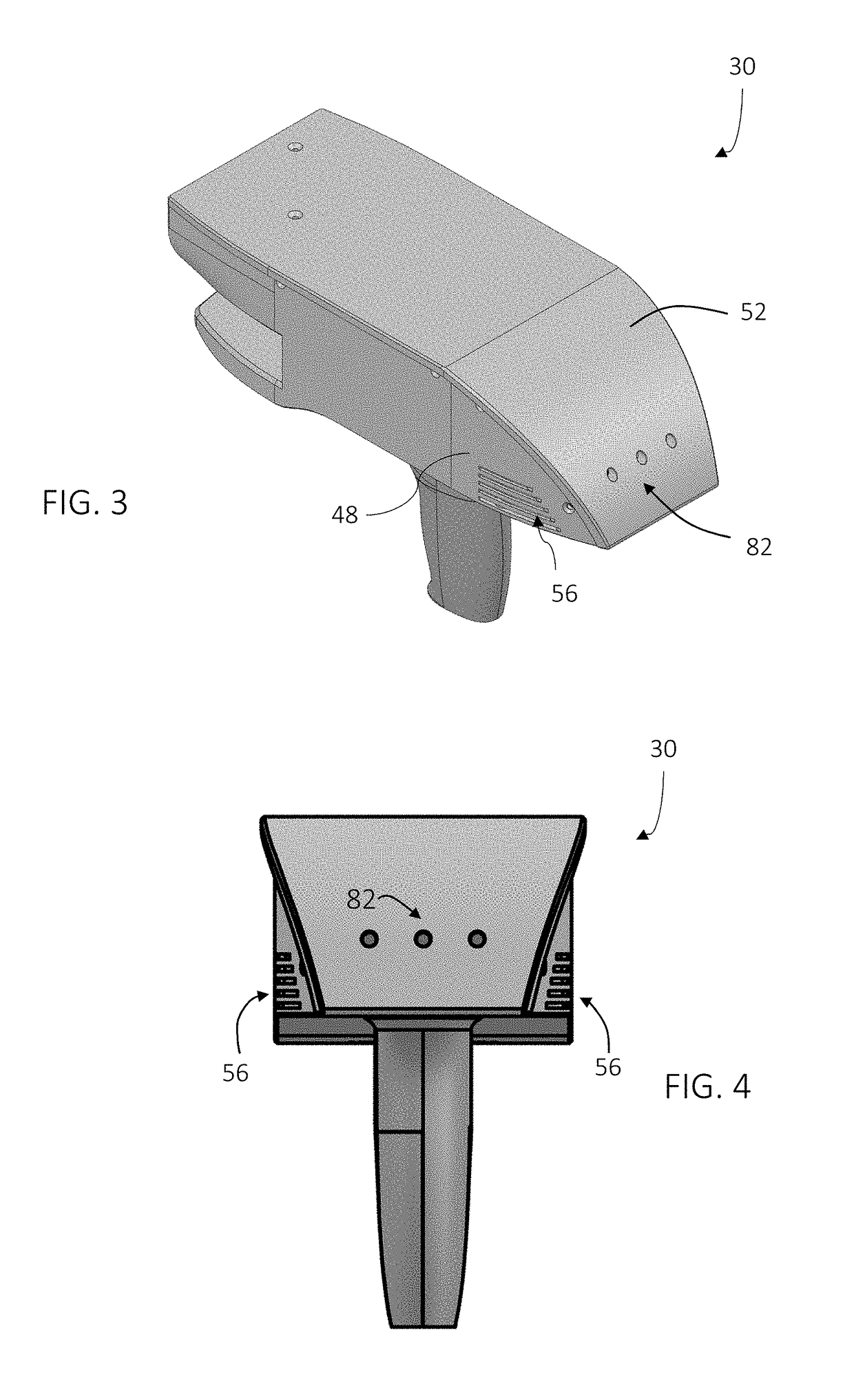
[0037]Referring now to FIGS. 1-7, an embodiment of a system 30 having a housing 32 that includes a body portion 34 and a handle portion 36. The handle 36 may include an actuator 38 that allows the operator to interact with the system 30. In the exemplary embodiment, the body 34 includes a generally rectangular center portion 35 with a slot 40 formed in an end 42. The slot 40 is at least partially defined by a pair walls 44, 46 that are angled towards a second end 48. As will be discussed in more detail herein, a portion of a two-dimensional scanner 50 is arranged between the walls 44, 46. The walls 44, 46 are angled to allow the scanner 50 to operate by emitting a light over a large angular area without interference from the walls 44, 46. As will be discussed in more detail...


PUM


Abstract

A system and method of generating a two-dimensional (2D) image of an environment is provided. The system includes a housing having a body and a handle. A 2D scanner is disposed in the body and has a light source, an image sensor and a controller, the light source steers a beam of light within a first plane to illuminate object points in the environment. The image sensor is arranged to receive light reflected from the object points and the controller determines a distance value to at least one of the object points. An inertial measurement unit is provided having a 3D accelerometer and a 3D gyroscope. One or more processors are responsive to executable instructions for generating a 2D image of the environment in response to an activation signal from an operator and based at least in part on the distance values and the signal.

Description

CROSS-REFERENCE TO RELATED APPLICATIONS[0001]The present application is a nonprovisional application of U.S. Provisional Application Ser. No. 62 / 477,667 filed on Mar. 28, 2017, the contents of which are incorporated by reference herein.BACKGROUND[0002]The present application is directed to a system that optically scans an environment, such as a building, and in particular to a portable system that generates two-dimensional floorplans of the scanned environment.[0003]The automated creation of digital two-dimensional floorplans for existing structures is desirable as it allows the size and shape of the environment to be used in many processes. For example, a floorplan may be desirable to allow construction drawings to be prepared during a renovation. Such floorplans may find other uses such as in documenting a building for a fire department or to document a crime scene.[0004]Existing measurement systems typically use a scanning device that determines coordinates of surfaces in the env...

Claims


Application Information

Patent Timeline
IPC IPC(8): G06F17/50G09B25/04G01B11/25
CPCG06F17/5004G09B25/04G01B11/2518G06T11/60G01C3/08G01C15/008G01S17/42G01S17/87G01S17/89G01S7/4808G01S17/86G01C21/1656G06F30/13
Inventor SANTOS, JOAOFRANK, ALEKSEJRAMADNEH, AHMADRAAB, SIMONZWEIGLE, OLIVERWHITE, DERIK J.
Owner FARO TECH INC
Learn More