Supercharge Your Innovation With Domain-Expert AI Agents!

Power conversion device and vehicle drive system to which same is applied

a technology of power conversion device and vehicle drive, which is applied in the direction of locomotive propulsion type, transportation and packaging, locomotives, etc., to achieve the effect of achieving estimation and calculation in a short tim

Active Publication Date: 2018-10-04
MITSUBISHI ELECTRIC CORP
View PDF7 Cites 11 Cited by
  • Summary
  • Abstract
  • Description
  • Claims
  • Application Information

AI Technical Summary

Benefits of technology

The power conversion device described in this patent has a control unit that can generate two switching signals with different frequencies. The device also includes a characteristic calculation unit that can estimate the resistance value of the electric motor and the dead time error based on the first and second operating characteristics of the device. This allows for the simultaneous estimation and calculation of both the resistance value and the dead time error. The device can also change the settings for control without changing the main circuit conditions, and the estimation and calculation can be done quickly.

Problems solved by technology

Due to the dead time, an output voltage error occurs, so that it is necessary to take a measure for compensating for the output voltage error.

Method used


Image

  • Power conversion device and vehicle drive system to which same is applied
  • Power conversion device and vehicle drive system to which same is applied
  • Power conversion device and vehicle drive system to which same is applied

Examples


embodiment 1

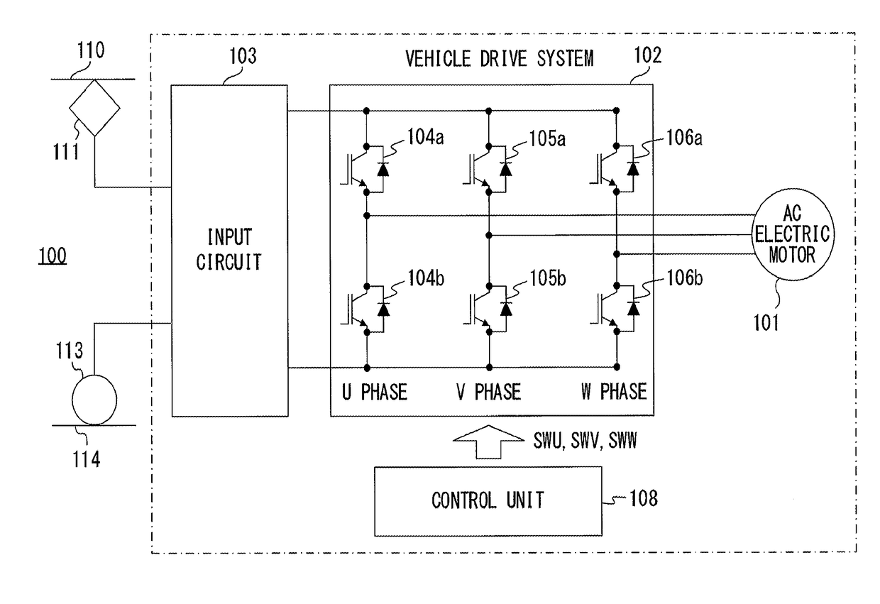
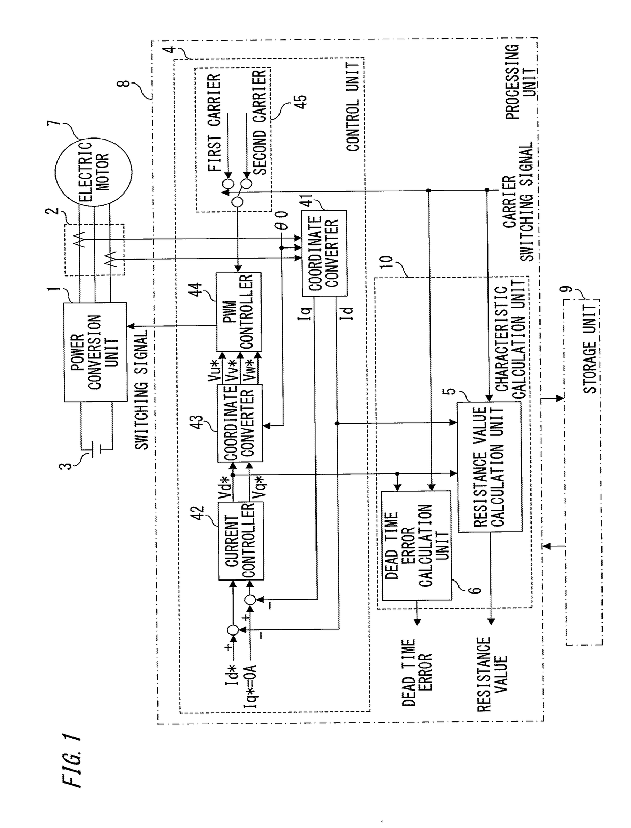
[0023]FIG. 1 is a block diagram showing the entire configuration of a power conversion device according to Embodiment 1 of the present invention. In FIG. 1, a power conversion unit 1: converts the voltage of a DC power supply 3 and supplies the converted voltage to an electric motor 7; has a bridge which is formed by connecting switching elements, such as IGBTs or MOSFETs, in series with each other between both electrodes of the DC power supply 3 and whose internal configuration is not shown since the internal configuration is publicly known; and has a function to convert DC power supplied from the DC power supply 3 to variable-voltage variable-frequency AC power and supply the AC power to the electric motor 7. The frequency of the variable-voltage variable-frequency AC power includes DC power of 0 Hz.

[0024]Current detection units 2 individually detect respective phase currents supplied to the electric motor 7 by the power conversion unit 1, and send the detected phase currents to a...

embodiment 2

[0114]FIG. 5 is a diagram showing the configuration of a power conversion device according to Embodiment 2 of the present invention. Embodiment 2 is different from Embodiment 1 in that whereas the first operating characteristic and the second operating characteristic are obtained under the condition of control in which the current detection value detected by each current detection unit 2 is caused to follow the current command value in Embodiment 1 described above, the first operating characteristic and the second operating characteristic are obtained under a condition of control in which the voltage command value is made constant in Embodiment 2. Hereinafter, a specific configuration and an operation of estimation and calculation will be described.

[0115]A control unit 4A in FIG. 5 is configured such that fixed values, Vu*=V, Vv*=0, and Vw*=−V are provided as voltage command values to be inputted to a PWM controller 44A thereof, whereby a DC voltage of 2V is applied between the U ph...

embodiment 3

[0126]In Embodiment 3, the case where switching elements each composed of a wide bandgap semiconductor such as silicon carbide (SiC) as a material are used as the switching elements included in the power conversion unit 1 in the above embodiments, will be described.

[0127]The configuration in a drawing is the same as in the cases of the above embodiments, and thus the description thereof is omitted here.

[0128]The switching elements used in the power conversion unit 1 are generally semiconductor transistor elements (IGBTs, MOSFETs, etc.) containing silicon (Si) as a material and semiconductor diode elements similarly containing silicon as a material, these semiconductor transistor elements being connected in reverse parallel. The technique described in the above embodiments can be used in a power convertor including the general switching elements.

[0129]Meanwhile, the technique described in the above embodiments is not limited to the switching elements formed with silicon as a material...


PUM


Abstract

A control unit is configured to generate a first switching signal based on a voltage command value and a first carrier and a second switching signal based on the voltage command value and a second different carrier, and a characteristic calculation unit estimates and calculates at least one of a resistance value of an electric motor and a dead time error, which is the difference between an effective value of a dead time and a set value of the dead time, based on a first operating characteristic of a power conversion unit obtained when switching elements are driven with the first switching signal and a second operating characteristic of the power conversion unit obtained when the switching elements are driven with the second switching signal. The resistance value of the electric motor and the dead time error can be quickly calculated and estimated by a common structure.

Description

TECHNICAL FIELD[0001]The present invention relates to a power conversion device that performs pulse width modulation (hereinafter, referred to as PWM) control and calculates an actual resistance value of an electric motor or an actual dead time error.BACKGROUND ART[0002]A variable-speed electric motor control device composed of a power conversion device has been applied to various fields including railway vehicles, elevators, electric vehicles, and general-purpose inverters. In such various fields, higher performance and further improvement of reliability, such as improvement of accuracy of output torque or speed control of an electric motor, high efficiency, low noise, and the like of the electric motor, are expected. For the improvement of control performance as described above, it is necessary to quickly obtain the circuit constant of the electric motor and appropriately design a control parameter.[0003]Meanwhile, the circuit constant of an electric motor is known to vary dependi...

Claims


Application Information

Patent Timeline
Patent Type & Authority Applications(United States)
IPC IPC(8): H02P27/08H02M7/5387H02M1/32H02M1/38
CPCH02P27/085H02M7/53871H02M1/32H02M1/38H02M2001/0009H02M2001/385B61C3/00H02M1/0009H02M1/385H02P27/08H02M7/5395
Inventor KATO, SHOYAMASHITA, YOSHINORI
Owner MITSUBISHI ELECTRIC CORP
Features
  • R&D
  • Intellectual Property
  • Life Sciences
  • Materials
  • Tech Scout
  • Unparalleled Data Quality
  • Higher Quality Content
  • 60% Fewer Hallucinations
Learn More