
Virtualization and orchestration of a radio access network

a radio access network and virtualization technology, applied in the field of wireless communication, can solve the problems of difficult to achieve, complicated management of precious spectrum, and additional frequency bands available for cellphones or other mobile terminals

Active Publication Date: 2018-10-04
COMMSCOPE TECH LLC
View PDF7 Cites 135 Cited by
  • Summary
  • Abstract
  • Description
  • Claims
  • Application Information

AI Technical Summary

Benefits of technology

The patent text describes a distributed radio access network (RAN) for wireless communications. The technical effect of the patent is to provide efficient use of existing spectrum for cellular data traffic, which has increased dramatically in recent years. The RAN can manage a multi-node network and handle such issues as addressing, to send packets of data between nodes. The specifications for E-UTRAN are developed and published by the 3GPP, and are incorporated by reference herein. The technical effect of the patent is to improve the management of the precious spectrum for cellular data traffic, which is a fixed resource.

Problems solved by technology

Radio spectrum is a fixed resource, so making any additional frequency bands available for cellphones, or other mobile terminals, come at the expense of other uses.
This makes it very difficult to accomplish; therefore, efficient use of the existing spectrum is very important.
As such, management of the precious spectrum has become very complex.
Hence, network deployment and maintenance are expensive, lengthy, and error-prone processes.
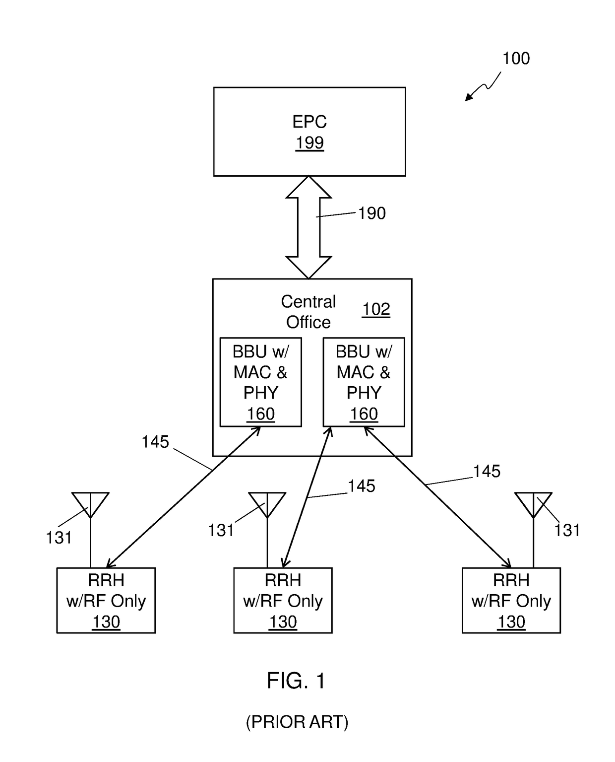
One key issue with a distributed RAN 100 architecture is latency.
If the overall latency for performing a specific function does not satisfy specific constraints imposed by the standard for the function, the system may fail, and communication between an eNB and a UE cannot be sustained.
Thus, latency constraints need to be satisfied in all operating conditions.
This requires hard, real-time, constraints on the processing of specific latency-constrained functions, or functions that have an impact on the overall system timeline.

Method used


Image

  • Virtualization and orchestration of a radio access network
  • Virtualization and orchestration of a radio access network
  • Virtualization and orchestration of a radio access network

Examples


Embodiment Construction

[0027]In the following detailed description, numerous specific details are set forth by way of examples in order to provide a thorough understanding of the relevant teachings. However, it should be apparent to those skilled in the art that the present teachings may be practiced without such details. In other instances, well known methods, procedures and components have been described at a relatively high-level, without detail, in order to avoid unnecessarily obscuring aspects of the present concepts. A number of descriptive terms and phrases are used in describing the various embodiments of this disclosure. These descriptive terms and phrases are used to convey a generally agreed upon meaning to those skilled in the art unless a different definition is given in this specification. Some descriptive terms and phrases are presented in the following paragraphs for clarity.

[0028]A Baseband Unit (BBU) is a portion of a base station of a radio access network (RAN) that implements most, or ...


PUM


Abstract

A distributed radio frequency communication system facilitates communication between wireless terminals and a core network. The system includes a group of remote radio units (RRUs). Each RRU of the group of RRUs is coupled to an antenna to communicate with at least some of the mobile terminals and includes electronic circuitry to perform at least a first portion of a first-level protocol of a radio access network (RAN) and communicate over a fronthaul link. The system also includes a baseband unit (BBU) coupled to the core network and the fronthaul link, and communicably coupled to the group of RRUs over the fronthaul link. The BBU includes electronic circuitry to assign one or more RRUs, selected from the group of RRUs, to a cluster of RRUs based on one or more parameters, and to perform at least a second-level protocol of the RAN.

Description

CROSS-REFERENCE TO RELATED APPLICATIONS[0001]The present application claims priority to U.S. Provisional Patent Application No. 62 / 245,113, entitled Methods for IP-based fronthaul in virtualized Radio Access Network, filed on Oct. 22, 2015, and to U.S. Provisional Patent Application No. 62 / 297,111, entitled Virtualization and Orchestration Methods for Radio-as-a-Service, filed on Feb. 18, 2016. The present application is also related to International Patent Application No. PCT / US2016 / 022114, entitled DISTRIBUTED RADIO ACCESS NETWORK WITH ADAPTIVE FRONTHAUL, filed on Mar. 11, 2016, which claims priority to U.S. Provisional Patent Application No. 62 / 131,337, entitled Methods for Radio-as-a-Service, filed on Mar. 11, 2015. The entire contents of all four afore-mentioned applications are hereby incorporated by reference herein for any and all purposes.BACKGROUNDTechnical Field[0002]The present subject matter relates to wireless communications. More specifically, the present subject matt...

Claims


Application Information

Patent Timeline
IPC IPC(8): H04B7/26H04B7/155H04W88/08H04W36/08G06F9/455H04W28/02H04W36/22
CPCH04B7/2606H04B7/15507H04W88/085H04W36/08G06F9/45558H04W28/0289H04W36/22G06F2009/45595H04W36/087H04W28/084
Inventor BARBIERI, ALANFERTONANI, DARIO
Owner COMMSCOPE TECH LLC
Learn More