Methods and devices for reducing circumferential pressure imbalances in an impeller side cavity of rotary machines
a technology of circumferential pressure imbalance and impeller side cavity, which is applied in the direction of non-positive displacement fluid engine, pump components, liquid fuel engine components, etc., can solve the problems of reducing efficiency, further narrowing down the preferred operating range, and flow instabilities, so as to improve rotational dynamic stability, encourage free circumferential flow, and alter the nature of flow dynamics
- Summary
- Abstract
- Description
- Claims
- Application Information
AI Technical Summary
Benefits of technology
Problems solved by technology
Method used
Image
Examples
second embodiment
DETAILED DESCRIPTION OF THE INVENTION
[0058]A cross-section view of the second embodiment of the present invention showing a fragment of a rotary machine next to the outlet of the impeller is depicted in FIG. 3. The benefits of the second embodiment include: (1) improved flow dynamics, (2) a more compact design, and (3) lower production costs.
[0059]During operation of the rotary machine, the rotating impeller (including impeller front disk (123)) propels the impeller main flow (127) towards the diffuser / volute (126) that may circumferentially encompass the impeller. Transit leakage flows through the annular gap (129) and has high tangential velocity. The annular leakage then moves into a radially more distal or distant region of the peripheral annular space (120) which is bounded by annular ring (120A). Fluid in impeller side cavity (124) is centrifuged outwardly and tangentially by rotating impeller front disk (123). Its outward and tangential momentum carries the fluid past the imp...
third embodiment
DETAILED DESCRIPTION OF THE INVENTION
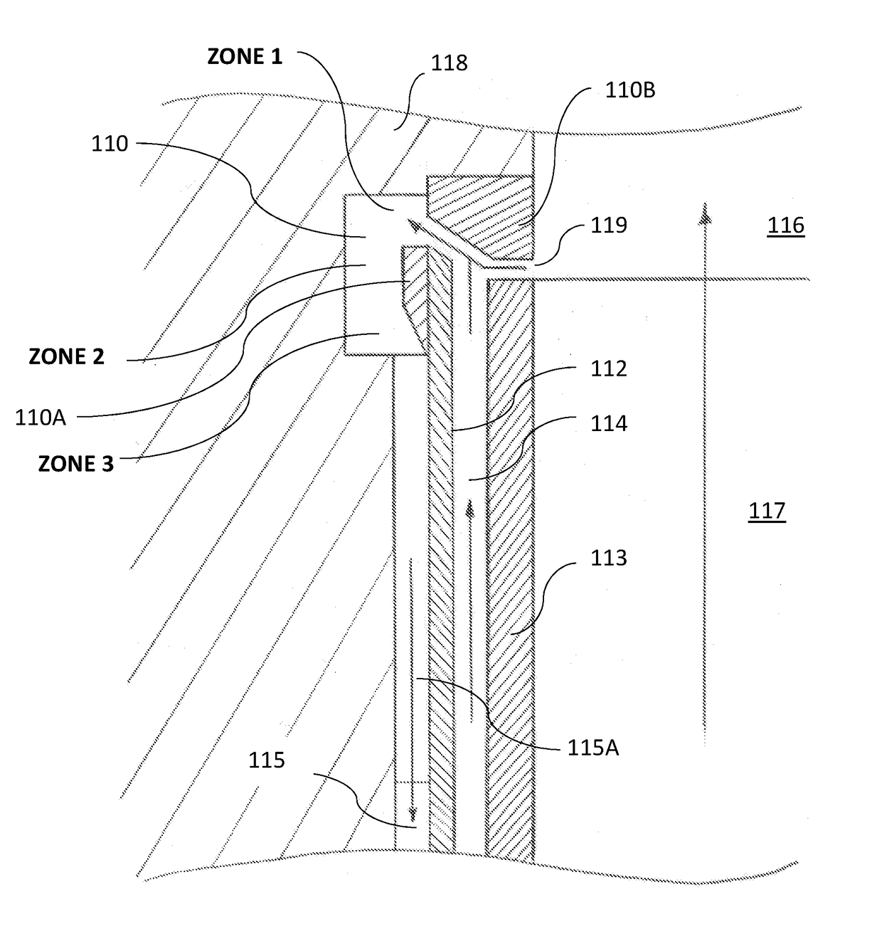
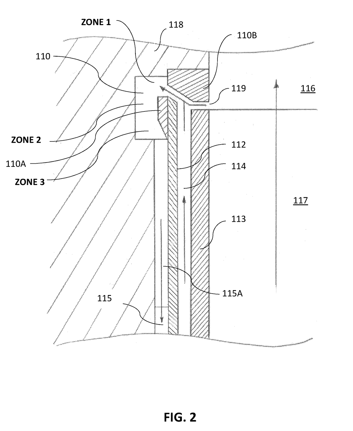
[0066]Several cross-sectional views of alternative embodiments of the third embodiment of the present invention are depicted in FIGS. 4A, 4B, and 4C. The benefits of the third embodiment of the present invention include: (1) an even more compact design, (2) further cost reduction opportunities.
[0067]The main fluid flow (137) through the rotary machine is propelled by impeller vanes having a front disk (133) defining in a periphery an impeller tip gap (139) with a peripheral annular ring (130A), which is fixedly attached to or formed together with a stationary housing (138). An annular subdividing disc (132) together with annular bypass channel (135) occupied partially of completely by redirecting vanes (135A) may be fixedly attached to the housing (138), together comprising a return channel for the secondary flow.
[0068]During operation, the rotating impeller including impeller front disk (133) urges the impeller main flow (137) into the diffuser / ...
PUM
 Abstract
Description
Claims
Application Information
 - R&D
- Intellectual Property
- Life Sciences
- Materials
- Tech Scout
- Unparalleled Data Quality
- Higher Quality Content
- 60% Fewer Hallucinations
Browse by: Latest US Patents, China's latest patents, Technical Efficacy Thesaurus, Application Domain, Technology Topic, Popular Technical Reports.
© 2025 PatSnap. All rights reserved.Legal|Privacy policy|Modern Slavery Act Transparency Statement|Sitemap|About US| Contact US: help@patsnap.com


