
Seal Ring

a sealing ring and sealing technology, applied in the field of sealing ring, can solve the problems of friction loss between the sealing ring and the shaft, drive loss of the hydraulic machine, etc., and achieve the effect of reducing friction loss and reducing oil leakag

Inactive Publication Date: 2018-10-11
RIKEN CO LTD
View PDF19 Cites 5 Cited by
  • Summary
  • Abstract
  • Description
  • Claims
  • Application Information

AI Technical Summary

Benefits of technology

The patent text describes a seal ring that can reduce both friction and oil leakage. This means that the seal ring can minimize the amount of energy needed to move an object and prevent lubricants from leaking out of a machine or device.

Problems solved by technology

During driving of the automatic transmission, a friction loss is caused between that seal ring and the shaft due to its rotation relative to the shaft.
Such a friction loss results in drive loss of the hydraulic machine.

Method used


Image

  • Seal Ring
  • Seal Ring
  • Seal Ring

Examples


modified example 1

4. Modified Example 1

[0088]FIG. 6 is a view showing a seal ring 101 according to Modified Example 1 of the above-mentioned embodiment. (A) of FIG. 6 is a plan view of the seal ring 101 and (B) of FIG. 6 is a cross-sectional view of the seal ring 101, which is taken along the line A-A′ of (A) of FIG. 6.

[0089]The seal ring 101 according to Modified Example 1 is provided with eight pockets 110. Unlike the pocket 10 of the seal ring 1 according to the embodiment, the pocket 110 has inclined surfaces. An inner circumferential surface 101b is connected to side surfaces 101c through the inclined surfaces, respectively. In the seal ring 101, a reduction in the friction loss due to the pockets 110 is achieved while keeping surface contact between the side surface 101c and the groove of the shaft.

[0090]Also in the seal ring 101 according to Modified Example 1, a recess region 21 similar to that of the seal ring 1 according to the above-mentioned embodiment is provided in a column portion 120 ...

modified example 2

5. Modified Example 2

[0091]FIG. 7 is a view showing a seal ring 201 according to Modified Example 2 of the above-mentioned embodiment. (A) of FIG. 7 is a plan view of the seal ring 201 and (B) of FIG. 7 is a partial, perspective view showing one of pockets 210 of the seal ring 201 in an enlarged state.

[0092]The pocket 210 provided in the seal ring 201 according to Modified Example 2 extends from an inflow port 211 provided in an inner circumferential surface 201b, along a region between an outer circumferential surface 201a and the inner circumferential surface 201b. The pocket 210 is configured such that a width and a depth from a side surface 201c become smaller in a direction away from the inflow port 211.

[0093]The seal ring 201 according to Modified Example 2 is configured such that oil flowing into the pocket 210 from the inflow port 211 does not flow out to the inner circumferential surface 201b while the opening of an oil channel is made smaller. The seal ring 201 has a confi...


PUM


Abstract

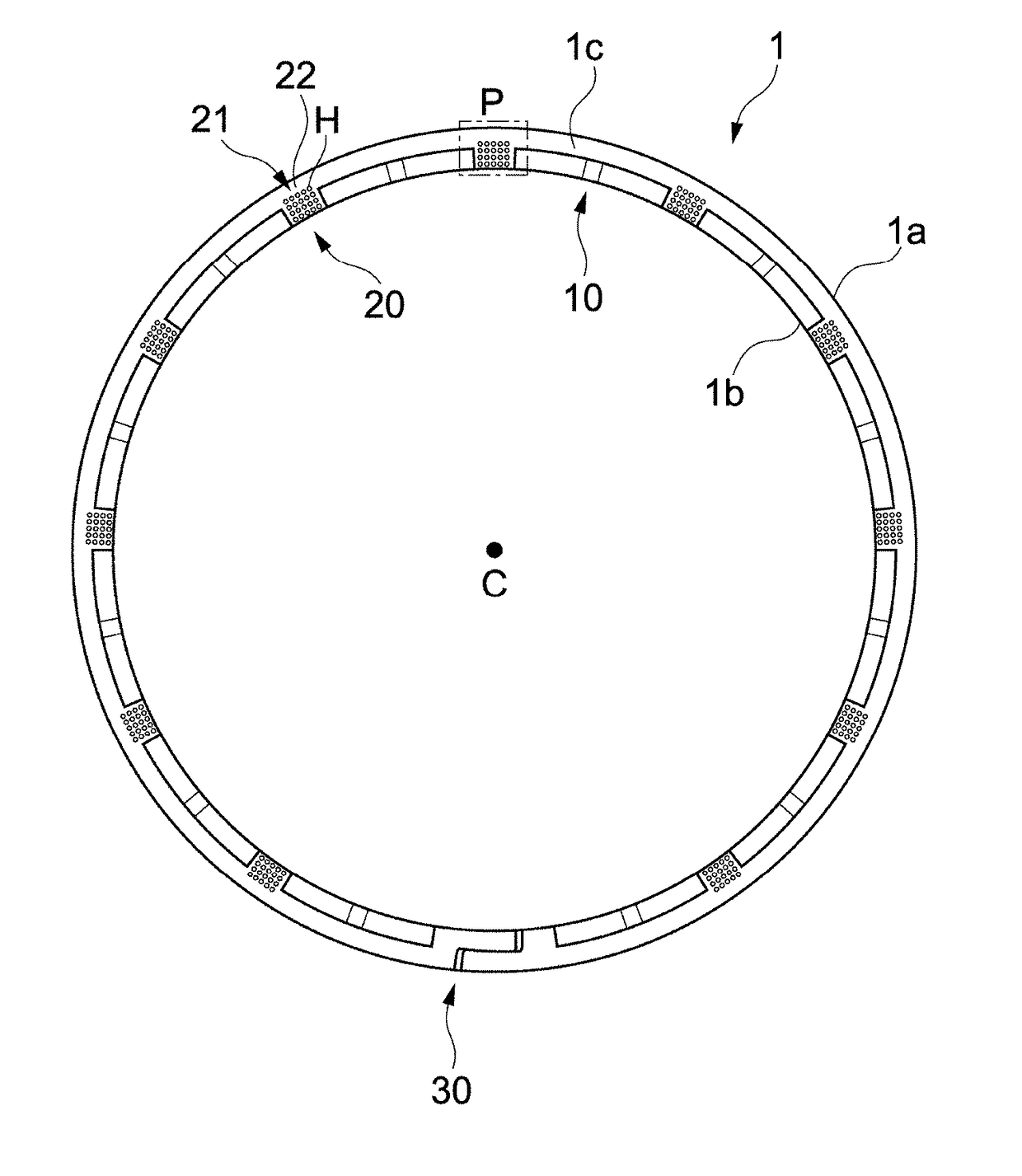
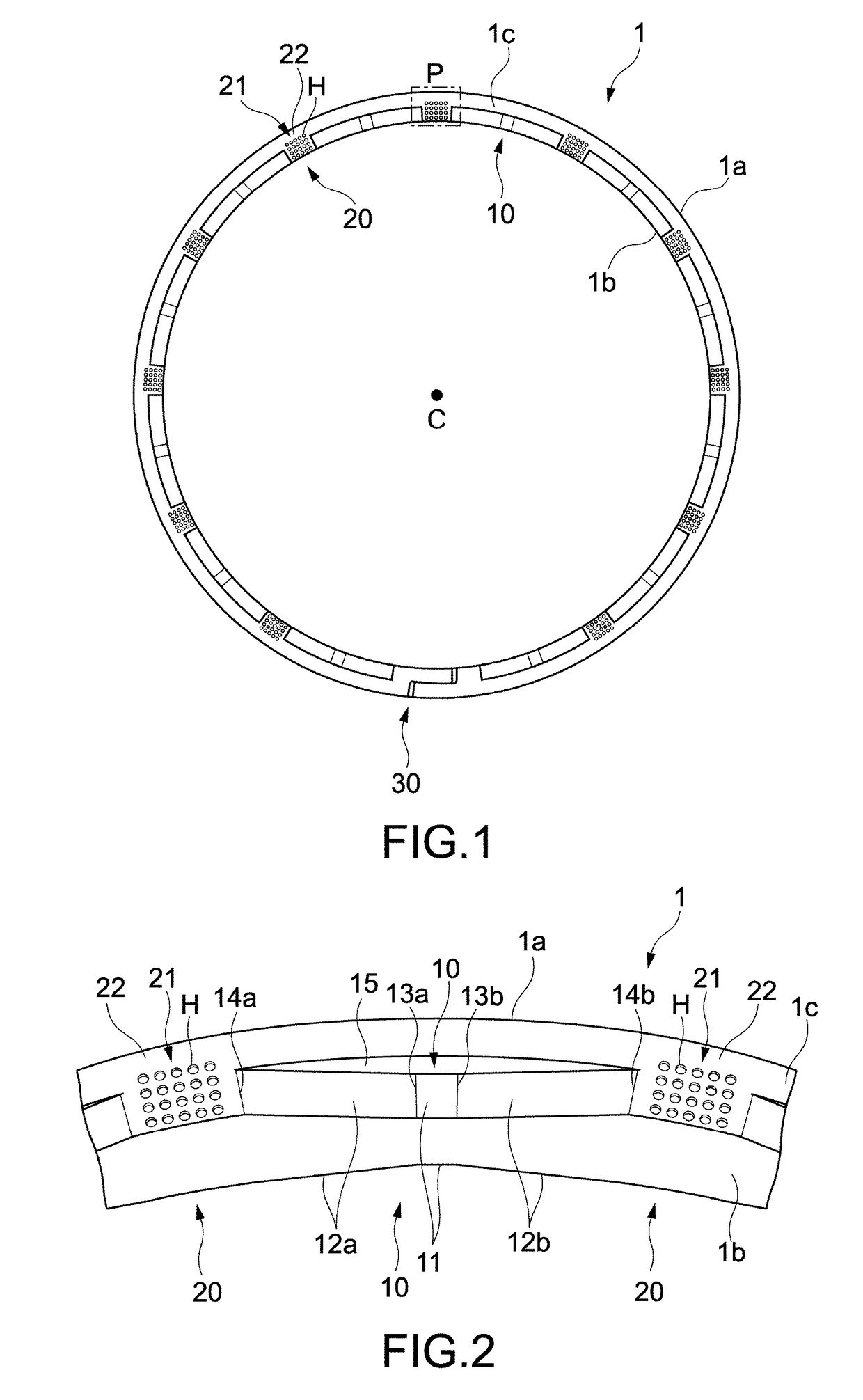
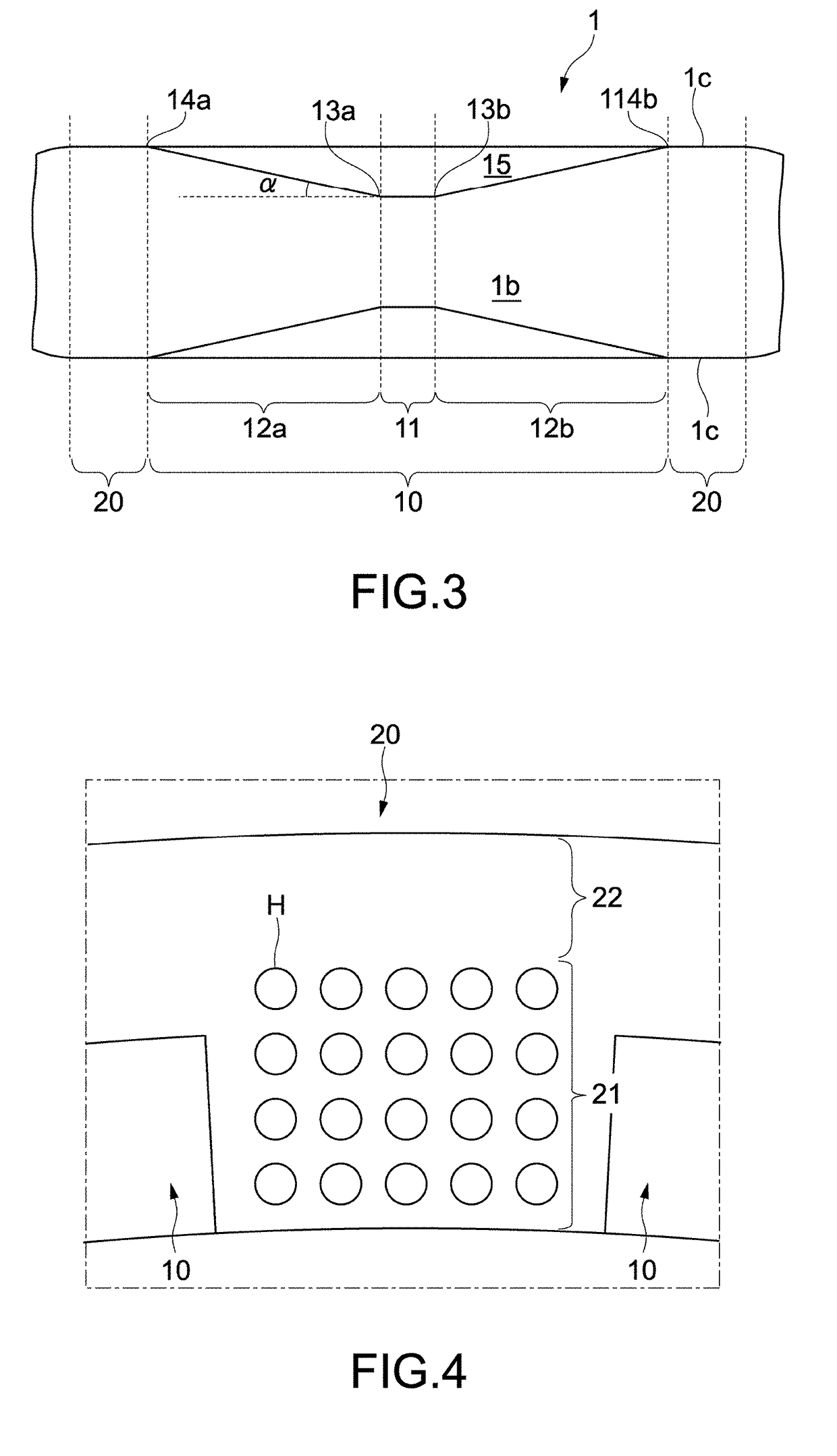
Object: To provide a seal ring capable of both reducing a friction loss and reducing oil leakage.Solving Means: The seal ring includes an inner circumferential surface, an outer circumferential surface, side surfaces, a plurality of pockets, and recess regions. The outer circumferential surface is opposed to the inner circumferential surface. The side surfaces are orthogonal to the inner circumferential surface and the outer circumferential surface. The plurality of pockets are provided, spaced apart from one another in at least one of the side surfaces. The recess regions are provided in the at least one of the side surfaces and includes a plurality of independent recesses. In this seal ring, it is possible to both reduce the friction loss and reduce the oil leakage due to a function of buffering oil by the recess region.

Description

TECHNICAL FIELD[0001]The present invention relates to a seal ring that can be used for a hydraulic machine and the like.BACKGROUND ART[0002]There are known automobiles equipped with various hydraulic machines such as hydraulic-type automatic transmissions. In those automobiles, there is a demand for reduction in drive loss of the hydraulic machines so as to improve fuel efficiency.[0003]Seal rings are used for the hydraulic-type automatic transmissions. The seal ring is fitted into a groove of a shaft inserted into a housing, and seals a gap between the housing and the shaft. During driving of the automatic transmission, a friction loss is caused between that seal ring and the shaft due to its rotation relative to the shaft.[0004]Such a friction loss results in drive loss of the hydraulic machine. Therefore, a technology for reducing the friction loss is desirable. Patent Literatures 1 to 5 have disclosed technologies for reducing the friction loss caused between the seal ring and t...

Claims


Application Information

Patent Timeline
Patent Type & Authority Applications(United States)
IPC IPC(8): F16J15/34
CPCF16J15/342F16J15/18F16J15/3272F16J15/3408F16J15/3412F16J15/3424F16J15/3428
Inventor OHYA, NAOHISAHIRAYAMA, DAISUKEKAWASAKI, TAKAHIRO
Owner RIKEN CO LTD
Learn More