
Surgical Screw and Fusion Device Using the Same

Active Publication Date: 2018-10-18
L&K BIOMED CO LTD
View PDF0 Cites 2 Cited by
  • Summary
  • Abstract
  • Description
  • Claims
  • Application Information

AI Technical Summary

Benefits of technology

The present invention provides a surgical screw that can easily lock without needing a separate locking mechanism. This reduces the number of tools needed to lock the screw and saves time for the surgeon.

Problems solved by technology

As such, various techniques for preventing the bone screw from being pulled out in various areas are considered and disclosed in the art, but there is a disadvantage that a separate locking mechanism should be used for this purpose.

Method used


Image

  • Surgical Screw and Fusion Device Using the Same
  • Surgical Screw and Fusion Device Using the Same
  • Surgical Screw and Fusion Device Using the Same

Examples


Embodiment Construction

[0025]The present invention has an object to provide a surgical screw capable of self-locking without a separate locking mechanism and a fusion device using the same.

[0026]Hereinafter, the present invention will be described in detail with reference to the accompanying drawings. In denoting reference numerals to constitutional elements of respective drawings, it should be noted that the same elements will be denoted by the same reference numerals although they are illustrated in different drawings. In the embodiments of the present invention, the publicly known functions and configurations that are judged to be able to make the purport of the present invention unnecessarily obscure will not be described.

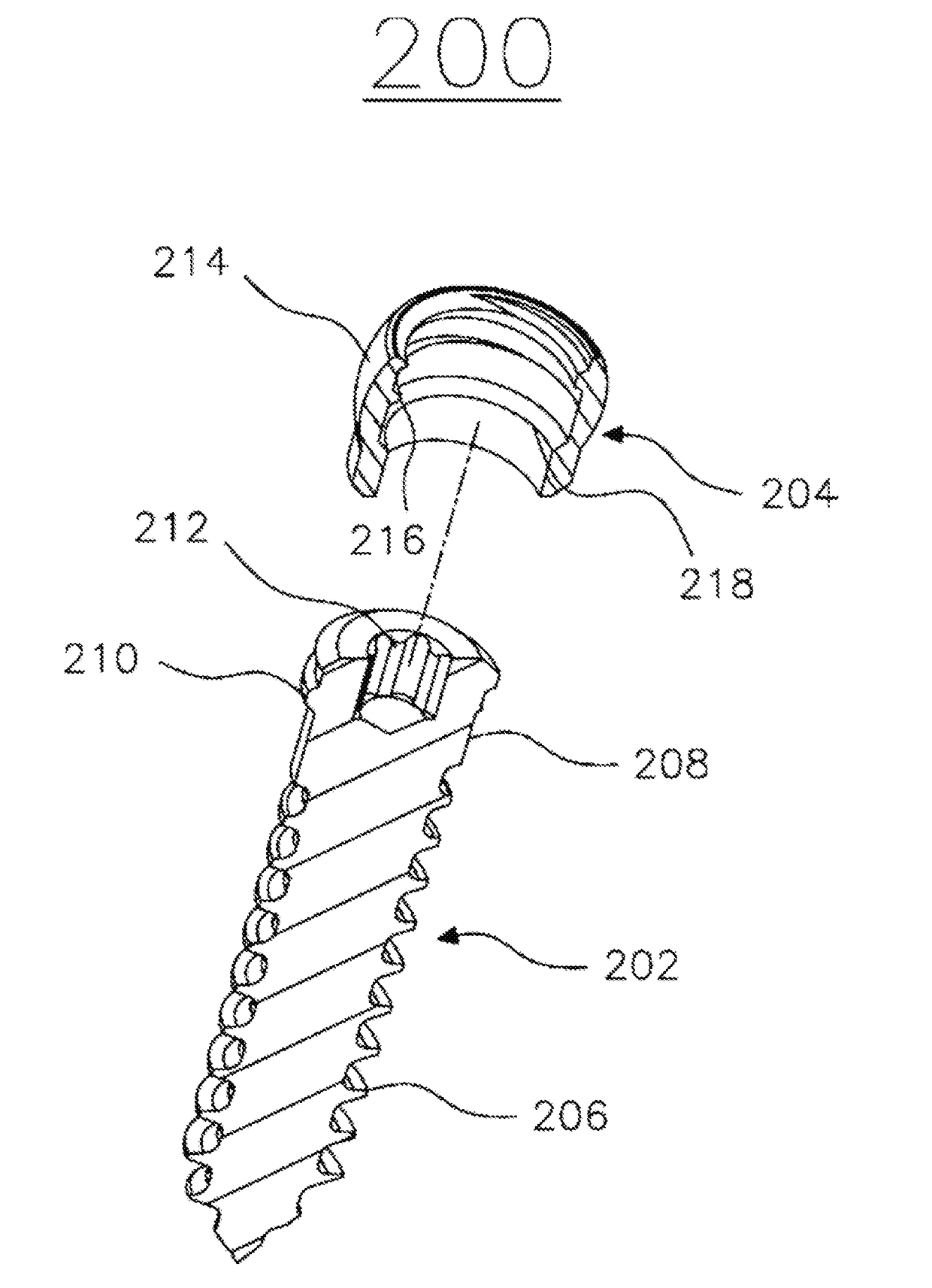
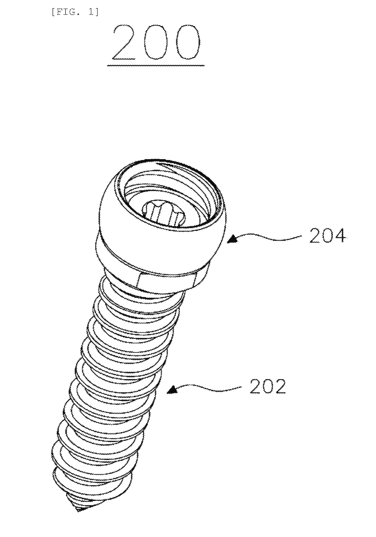
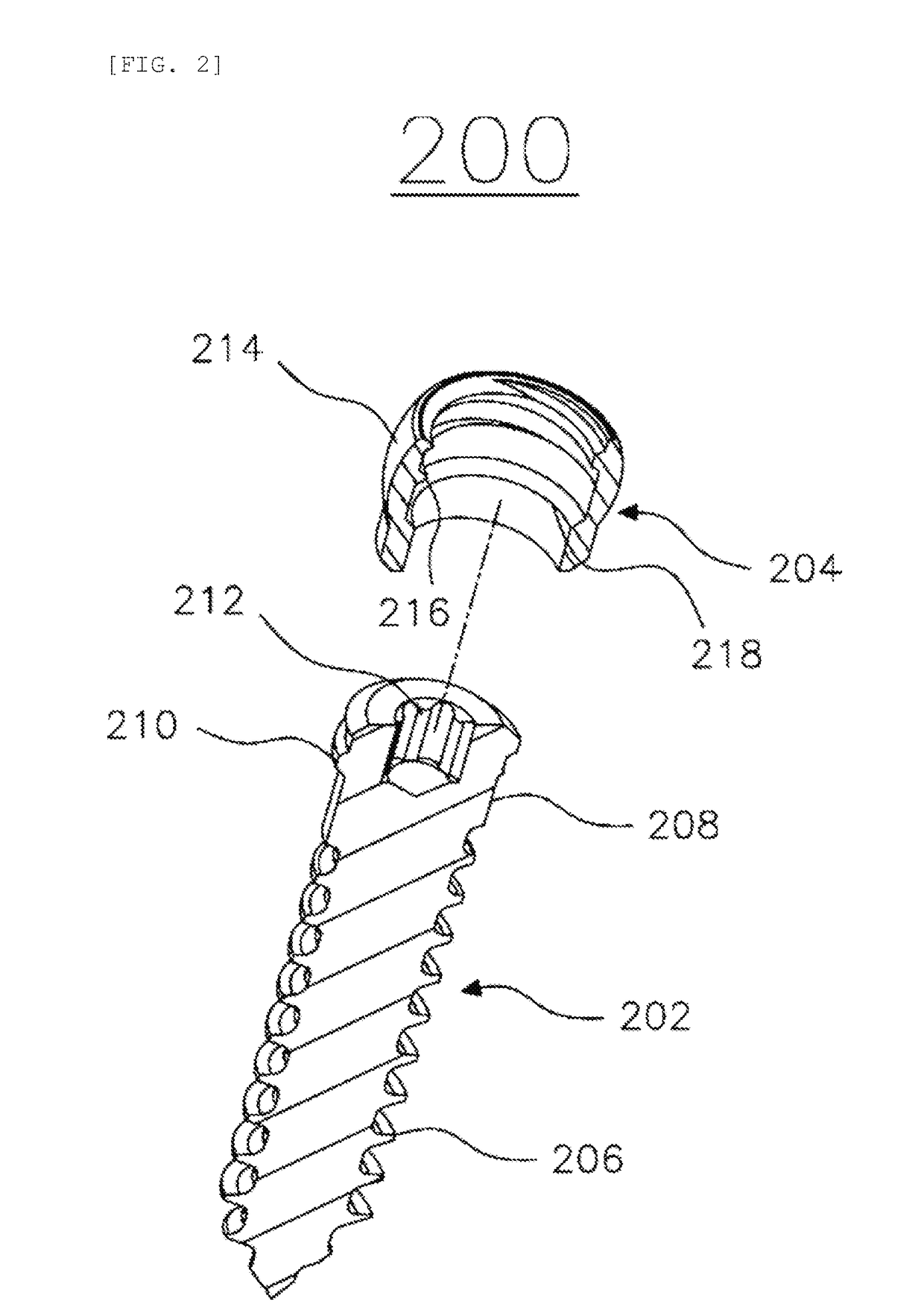
[0027]FIGS. 1 to 4 illustrate a surgical screw 200 according to an embodiment of the present invention. The surgical screw 200 basically includes a screw body 202 and a sleeve 204 fastened to the screw body 202.

[0028]The screw body 202 has a body main thread 206 formed on an outer ci...


PUM


Abstract

The present invention relates to a surgical screw capable of self-locking and a fusion device using the same. The screw includes: a screw body having a body main thread formed on an outer circumferential surface thereof, a body locking thread spaced apart from the body main thread with an offset portion interposed therebetween, and a body driving groove formed in the upper portion thereof; and a sleeve having a sleeve thread formed on an inner circumferential surface thereof to be screwed with the body locking thread, and a sleeve stopper spaced downwards from the sleeve thread so as to support the body locking thread. The surgical screw may also be included in a fusion device in a different form by coupling with a plate or a cage.

Description

TECHNICAL FIELD[0001]The present invention relates to a surgical screw and a fusion device using the same, and more particularly, to a surgical screw capable of self-locking and a fusion device using the same.BACKGROUND ART[0002]Various types of fasteners are used to fasten implants and other devices to bones. In a spinal field, bone screws are typically used in order to attach plates, rods, and the like of implants and devices to one or more vertebral bodies.[0003]Various techniques have been developed to fix the bone screws to the vertebral bodies, or prevent the bone screws from being separated from the plates or rods of the implants and devices. For example, U.S. Pat. No. 7,846,207 discloses a technique in which a cage may be inserted between vertebral bodies and bone screws may be attached to the vertebral bodies to fix the cage. The above patent proposes a method in which, a securing plate is further provided on a head side of the bone screw to prevent the bone screw from bein...

Claims


Application Information

Patent Timeline
IPC IPC(8): A61B17/80A61B17/70A61B17/86A61F2/44A61F2/30
CPCA61B17/8047A61B17/7058A61B17/8605A61F2/447A61F2/30749A61F2002/30622A61F2/4455A61F2002/30578A61F2002/30593A61F2002/30784A61F2002/30785A61F2002/30787A61B17/86A61F2/44A61B17/72A61B17/70
Inventor KANGCHOI, SUN KAK
Owner L&K BIOMED CO LTD
Features
  • Generate Ideas
  • Intellectual Property
  • Life Sciences
  • Materials
  • Tech Scout
  • Unparalleled Data Quality
  • Higher Quality Content
  • 60% Fewer Hallucinations
Learn More