
Docking unit and electronic apparatus system

a technology of electronic equipment and unit, applied in the field of electronic equipment system, can solve the problems of limited function extension performance, increased heat generation amount of battery unit or arithmetic unit built therein, increased processing load, etc., and achieve the effect of extending the function of electronic equipment and heat dissipation performance of portable information equipmen

Active Publication Date: 2018-10-25
LENOVO PC INT
View PDF14 Cites 2 Cited by
  • Summary
  • Abstract
  • Description
  • Claims
  • Application Information

AI Technical Summary

Benefits of technology

The present invention provides a docking unit that can secure the heat dissipation performance of a portable information apparatus while also extending the function of the electronic apparatus in which an extension unit is mounted on the portable information apparatus. The docking unit has a docking portion that can connect to the electronic apparatus, a holding portion that can hold the portable information apparatus in a specific position, and a forcibly moving portion that can move the extension unit in a certain direction to create space between the back of the portable information apparatus and the mounting surface of the extension unit. Overall, the docking unit ensures optimal heat dissipation performance for the portable information apparatus while expanding the capabilities of the electronic apparatus.

Problems solved by technology

Therefore, the extension unit has also been demanded to achieve the same reduction in thickness, size, and weight as that of the portable information apparatus, so that the function extension performance has been limited.
However, when the portable information apparatus is connected to such external devices, so that the processing load increases, the heat generation amount from a battery unit or an arithmetic unit built therein increases.
In the portable information apparatus, however, the extension unit is mounted on the back surface serving as a main heat dissipation portion, and therefore sufficient heat dissipation performance may not be achievable.

Method used


Image

  • Docking unit and electronic apparatus system
  • Docking unit and electronic apparatus system
  • Docking unit and electronic apparatus system

Examples


Embodiment Construction

[0027]Hereinafter, a docking unit according to the present invention is described in detail giving an embodiment suitable in the relationship with an electronic apparatus system having the docking unit with reference to the attached drawings.

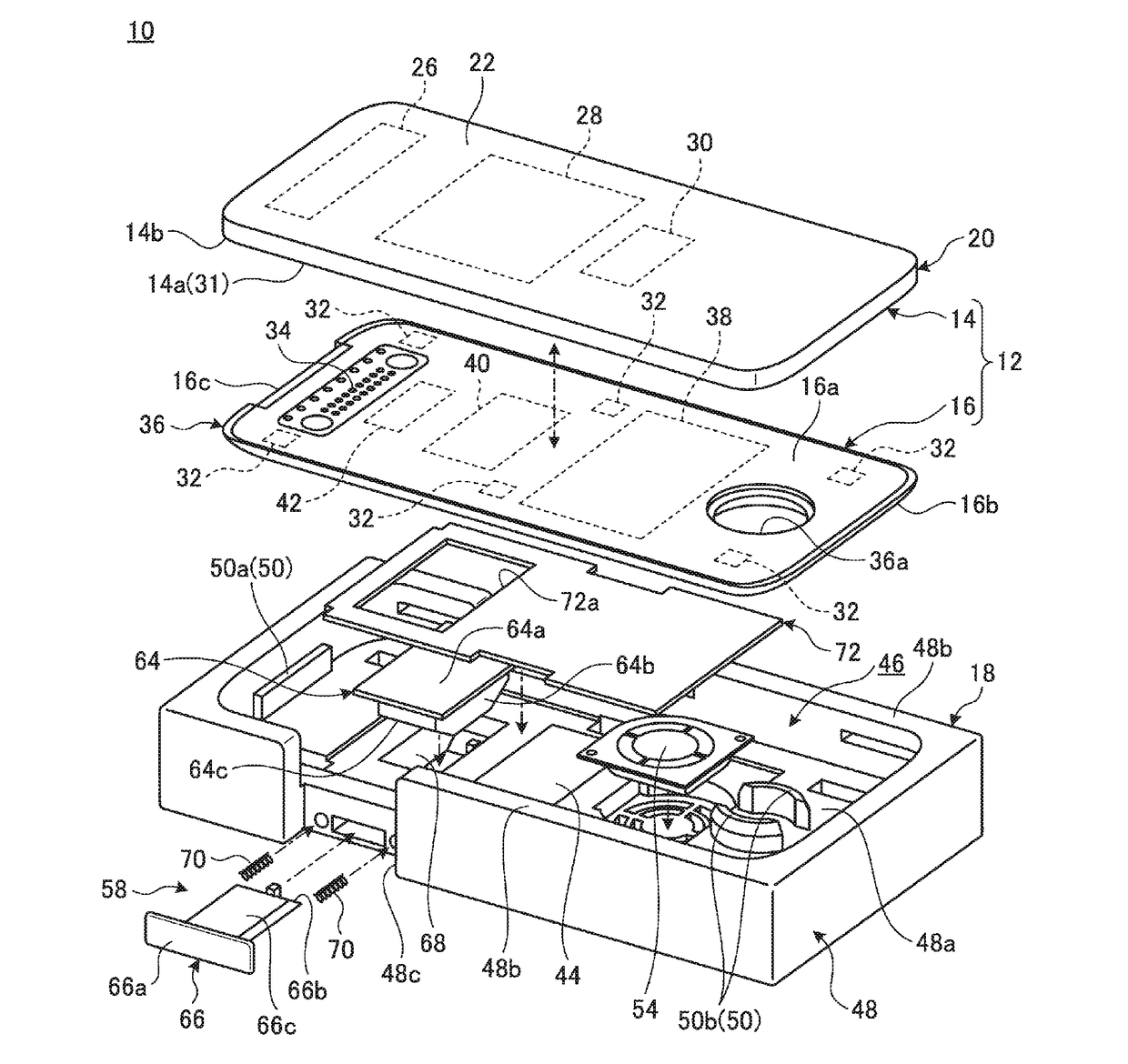
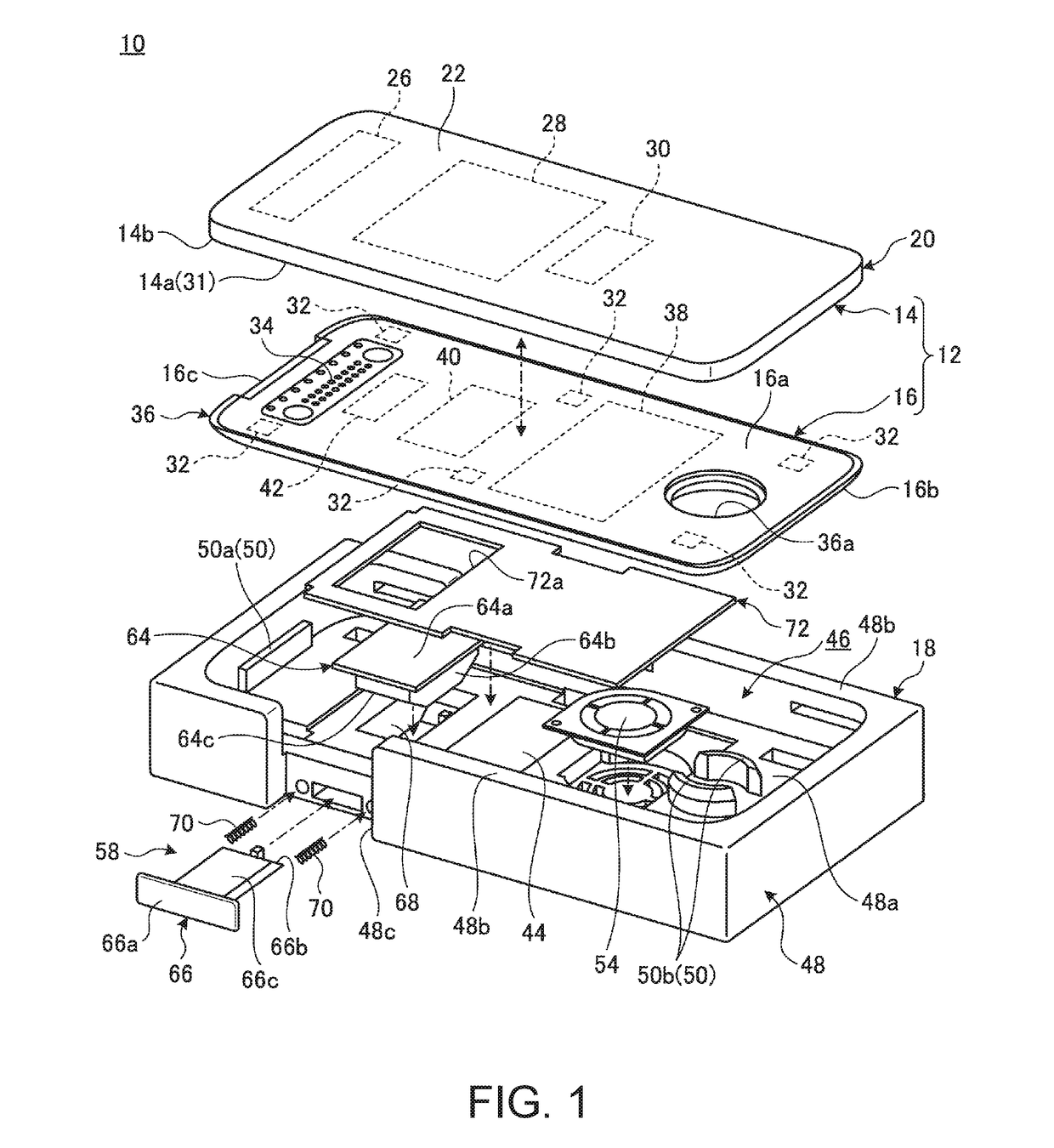
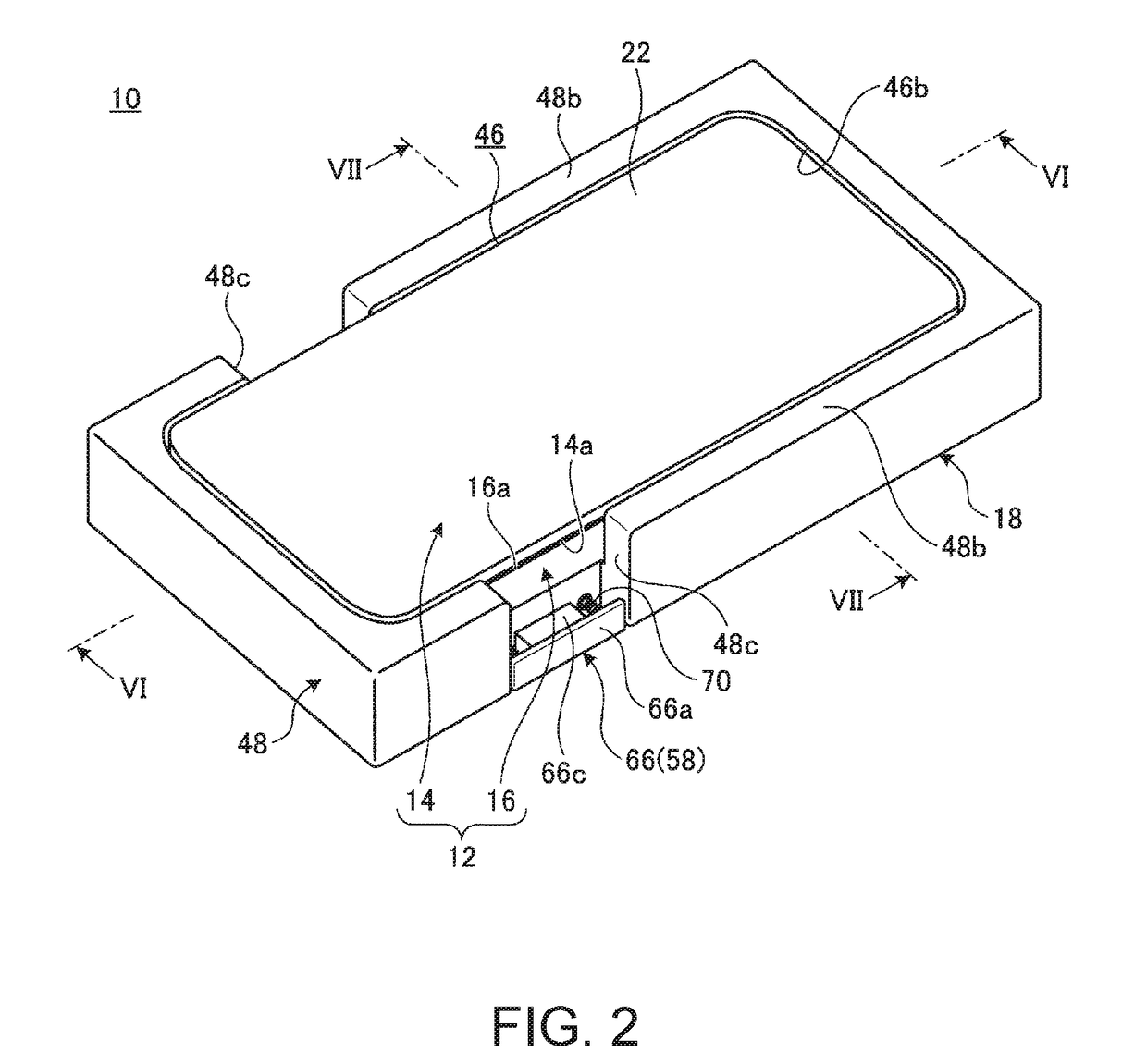
[0028]FIG. 1 is an exploded perspective diagram of an electronic apparatus system 10 according to the present disclosure. FIG. 2 is a perspective diagram of the electronic apparatus system 10 of the present disclosure. As illustrated in FIG. 1, the electronic apparatus system 10 has a portable information apparatus 14 and an extension unit 16 which are mounted to each other to configure an electronic apparatus 12, and a docking unit 18. As illustrated in FIG. 2, the electronic apparatus 12 can be docked with the docking unit 18.

[0029]First, the configuration of the electronic apparatus 12 is described. FIG. 3 is a configuration diagram of the electronic apparatus 12 of the present disclosure viewed from the three surfaces of the plane, the back ...


PUM


Abstract

To provide a docking device capable of securing heat dissipation performance of a portable information apparatus while extending the function of an electronic apparatus in which an extension unit is mounted on the portable information apparatus, and an electronic apparatus system having the docking device. A docking unit that has a docking portion capable of docking an electronic apparatus in which a mounting surface of an extension unit is detachably mounted on a back surface of the portable information apparatus, a holding portion holding the portable information apparatus at a predetermined position in a docking direction when the electronic apparatus is docked with the docking portion, and a forcibly moving portion forcibly moving the extension unit in the docking direction when the electronic apparatus is docked with the docking portion.

Description

FIELD OF THE INVENTION[0001]The present invention relates to a docking unit capable of docking an electronic apparatus in which an extension unit is mounted on a portable information apparatus and an electronic apparatus system having the docking unit.BACKGROUND OF THE INVENTION[0002]In a portable information apparatus, such as a smart phone and tablet PC, the thickness, the size, and the weight thereof have further decreased, so that functions to be mounted thereon have been limited in many cases. For example, Patent Document 1 discloses a configuration which enables extension of functions, such as a battery function, by mounting an extension unit having approximately the same shape as that of a portable information apparatus on the back surface of the portable information apparatus.[0003][Patent Document 1] Japanese Patent Application Laid-Open No. 2017-45043SUMMARY OF THE INVENTION[0004]The extension unit described in Patent Document 1 is used or carried in the state of being mou...

Claims


Application Information

Patent Timeline
IPC IPC(8): G06F1/16G06F13/40G06F1/20
CPCG06F1/1632G06F1/206G06F13/4081H04M1/04G06F1/203
Inventor NAKAMURA, FUSANOBU
Owner LENOVO PC INT
Learn More