A distribution transformer

A technology for distribution transformers and transformers, applied in the field of transformers, can solve problems such as poor cooling effect and transformer oil cooling, and achieve good heat conduction effects, accelerated cooling, and accelerated cooling effects

Active Publication Date: 2021-10-15
江苏龙创电气有限公司
View PDF4 Cites 0 Cited by
  • Summary
  • Abstract
  • Description
  • Claims
  • Application Information

AI Technical Summary

Problems solved by technology

[0004] The purpose of the present invention is to solve the problem that most of the internal transformer oil is in a static state, and the cooling fins and fans cannot fully cool the transformer oil, resulting in a poor cooling effect

Method used


Image

  • A distribution transformer
  • A distribution transformer
  • A distribution transformer

Examples


Embodiment 1

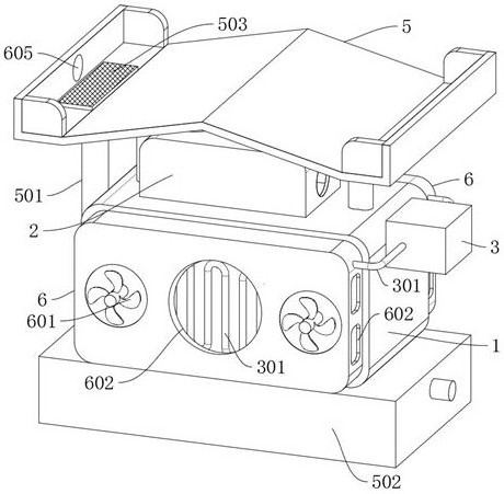
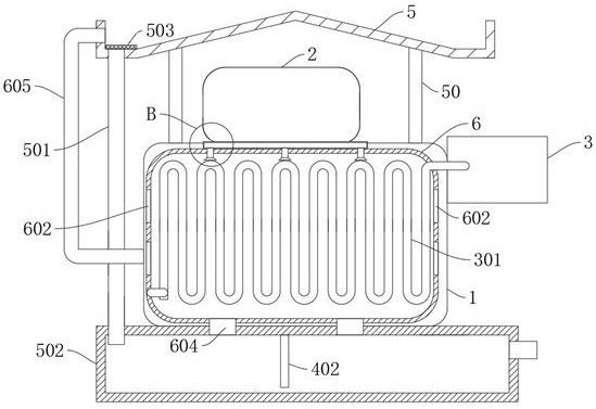
[0032] refer to Figure 1-8 , a distribution transformer, including a transformer device 1, a cooling device 3, and also includes: a return-shaped tube 301, which is arranged on the inside and outside of the transformer device 1, and the output and input ends of the return-shaped tube 301 are connected to the cooling device 3; stirring The assembly is connected in the transformer equipment 1; the water tank 502 is fixedly connected to the bottom of the transformer equipment 1; the protection box 2 is fixedly connected to the top of the transformer equipment 1; the piston cylinder 4 is fixedly connected in the protection box 2, wherein the piston cylinder 4 The water inlet pipe 402 and the water outlet pipe 403 are fixedly connected, and the end of the water inlet pipe 402 away from the piston cylinder 4 leads to the water tank 502; the nozzle 404 is fixedly connected to the end of the water outlet pipe 403 away from the piston cylinder 4, wherein the nozzle 404 is curved toward...

Embodiment 2

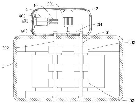
[0041] refer to image 3 , 4 . On the rotating shaft 202, one end of the rotating shaft 202 runs through the transformer device 1, the rotating shaft 202 and the output end of the motor 201 are connected by a belt 204; the motor 201 is inside the protection box 2, the crankshaft 40 is fixedly connected to the rotating shaft 202, and a push rod is slidingly connected in the piston barrel 4 401, one end of the push rod 401 is rotatably connected to the crankshaft 40;

[0042] The rotation of the motor 201 drives the rotating shaft 202 to rotate through the belt 204, and the rotating shaft 202 then drives the stirring fan 203 to stir the transformer oil in the transformer equipment 1;

[0043] At the same time, the motor 201 rotates to drive the crankshaft 40 to rotate, and the crankshaft 40 drives the push rod 401 to reciprocate in the piston barrel 4. When the crankshaft 40 pulls the push rod 401, the water in the water tank 502 is drawn into the piston barrel 4 through the w...

Embodiment 3

[0046] refer to Figure 4 , a distribution transformer, which is basically the same as that of Embodiment 2, furthermore: the stirring assembly is provided with four groups;

[0047] The four sets of stirring components are all connected to the output end of the motor 201 through the belt 204, and then rotated by the motor 201 to drive the four sets of stirring components to stir the transformer oil in the transformer equipment 1 at the same time, so that the transformer oil is more active and fully integrated with the transformer equipment. 1 in contact with the return-shaped tube 301 to improve the cooling efficiency and effect of the transformer oil.


PUM


Abstract

The invention discloses a distribution transformer, which belongs to the technical field of transformers. A distribution transformer includes transformer equipment and cooling equipment, and further includes: loop tubes, which are arranged on the inside and outside of the transformer device, and the output ends and the input ends of the loop tubes are both connected to the cooling device; a stirring component is connected to In the transformer equipment; the present invention arranges a loop tube inside and outside the transformer device, uses a cooling device to discharge cooling liquid into the loop tube, absorbs the heat inside the transformer device, and conducts the heat inside the transformer device to the outside of the transformer device, At the same time, water is sprayed to the outer loop tube through the piston cylinder to dissipate heat again, thereby accelerating the cooling of the transformer oil. At the same time, the transformer oil is stirred with the stirring fan blade, so that the transformer oil is fully contacted with the internal loop tube, and the transformer is fully cooled. , improve the cooling effect and efficiency.

Description

technical field [0001] The invention relates to the technical field of transformers, in particular to a distribution transformer. Background technique [0002] Transformers are classified according to cooling methods: there are oil-immersed transformers and dry-type transformers; oil-immersed transformers are a new type of high-performance transformer with a more reasonable structure and better performance. Oil is used as the main insulation method of the transformer and relies on oil for cooling. Medium; The main components of the transformer include iron core, winding, oil tank, oil conservator, respirator, pressure relief valve, radiator, insulating bushing, tap changer, gas relay, thermometer, oil purifier, oil level gauge, etc. [0003] When the transformer is working, it will generate heat, which will increase the temperature of the transformer and correspondingly increase the temperature of the internal transformer oil. After the transformer oil heats up, it will acce...

Claims


Application Information

Patent Timeline
Patent Type & Authority Patents(China)
IPC IPC(8): H01F27/16H01F27/14H01F27/08H01F27/02B08B5/02
CPCB08B5/02H01F27/02H01F27/025H01F27/085H01F27/14H01F27/16
Inventor 沈宝春
Owner 江苏龙创电气有限公司
Why Eureka
Try Eureka