Pulse estimation device, pulse estimation system, and pulse estimation method

a pulse estimation and pulse technology, applied in the field of pulse estimation devices, can solve problems such as problems such as difficulty in estimating a pulse stably, inability to produce good pulse signals, and inability to accurately estimate pulses

Active Publication Date: 2018-11-01
PANASONIC INTELLECTUAL PROPERTY MANAGEMENT CO LTD
View PDF0 Cites 17 Cited by
  • Summary
  • Abstract
  • Description
  • Claims
  • Application Information

AI Technical Summary

Benefits of technology

[0006]The present disclosure is proposed in consideration of these problems of the related art, a main object of the present disclosure is to provide a pulse estimation device, a pulse estimation system, and a pulse estimation method which can stably estimate a pulse based on an image data suitable for extracting a pulse signal.

Problems solved by technology

Therefore, there are problems in that, depending on performance of the camera or imaging condition (brightness or the like), a good pulse signal cannot be extracted (that is, an image data suitable for extracting the pulse signal cannot be acquired), and it becomes difficult to estimate a pulse stably.
These problems can similarly occur also in a case of using the related art as disclosed in PTL 2 as a method of detecting the pulse from the pulse signal.

Method used


Image

  • Pulse estimation device, pulse estimation system, and pulse estimation method
  • Pulse estimation device, pulse estimation system, and pulse estimation method
  • Pulse estimation device, pulse estimation system, and pulse estimation method

Examples


first embodiment

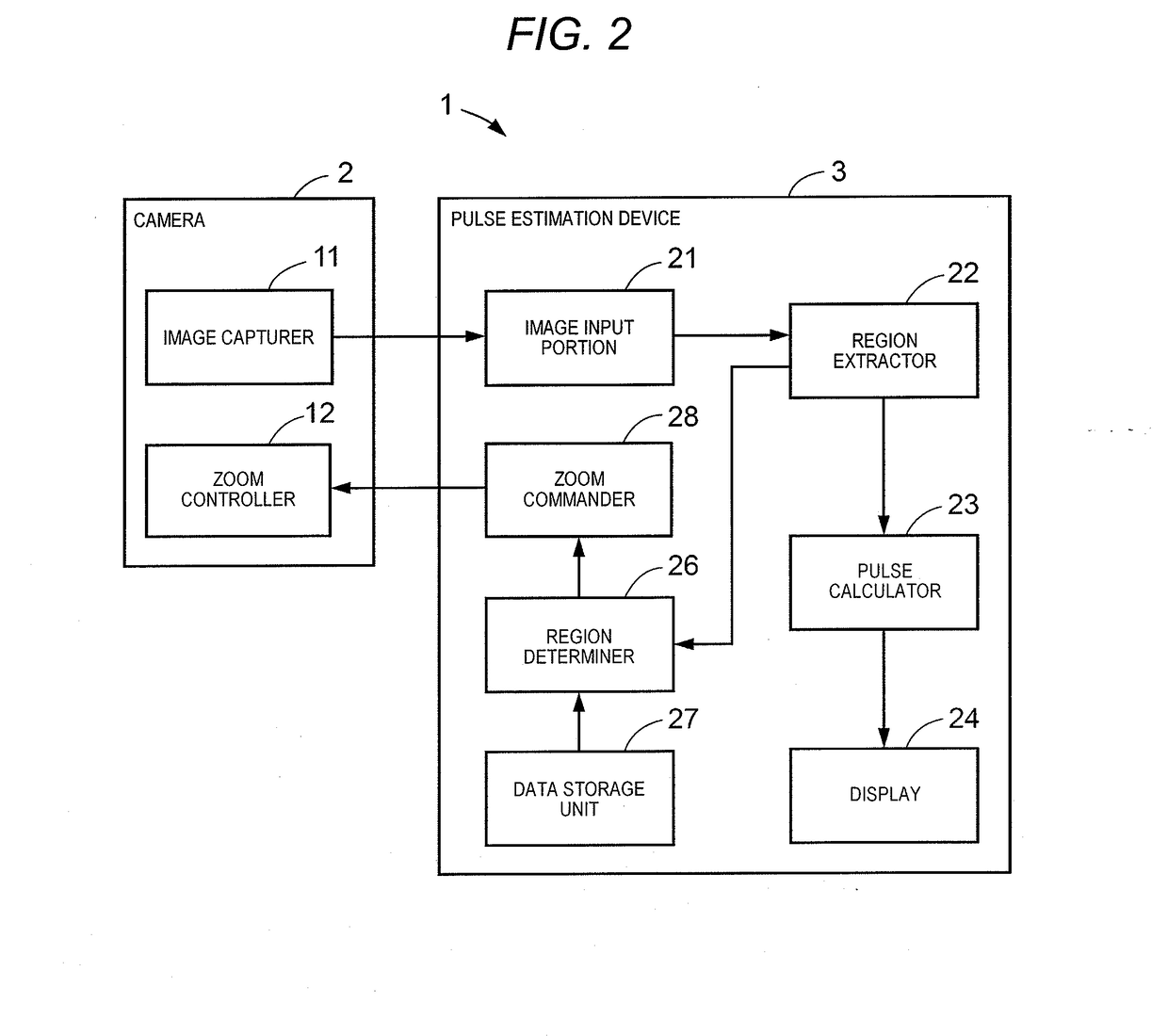
[0047]FIGS. 1 and 2 are respectively an overall configuration diagram and a functional block diagram of pulse estimation system 1 according to the first embodiment of the present disclosure. FIG. 3 is an explanatory diagram of a pulse extracting process by pulse calculator 23 of pulse estimation device 3. FIGS. 4A to 4C are explanatory diagrams of result of control by zoom commander 28 of pulse estimation device 3 shown in FIG. 2.

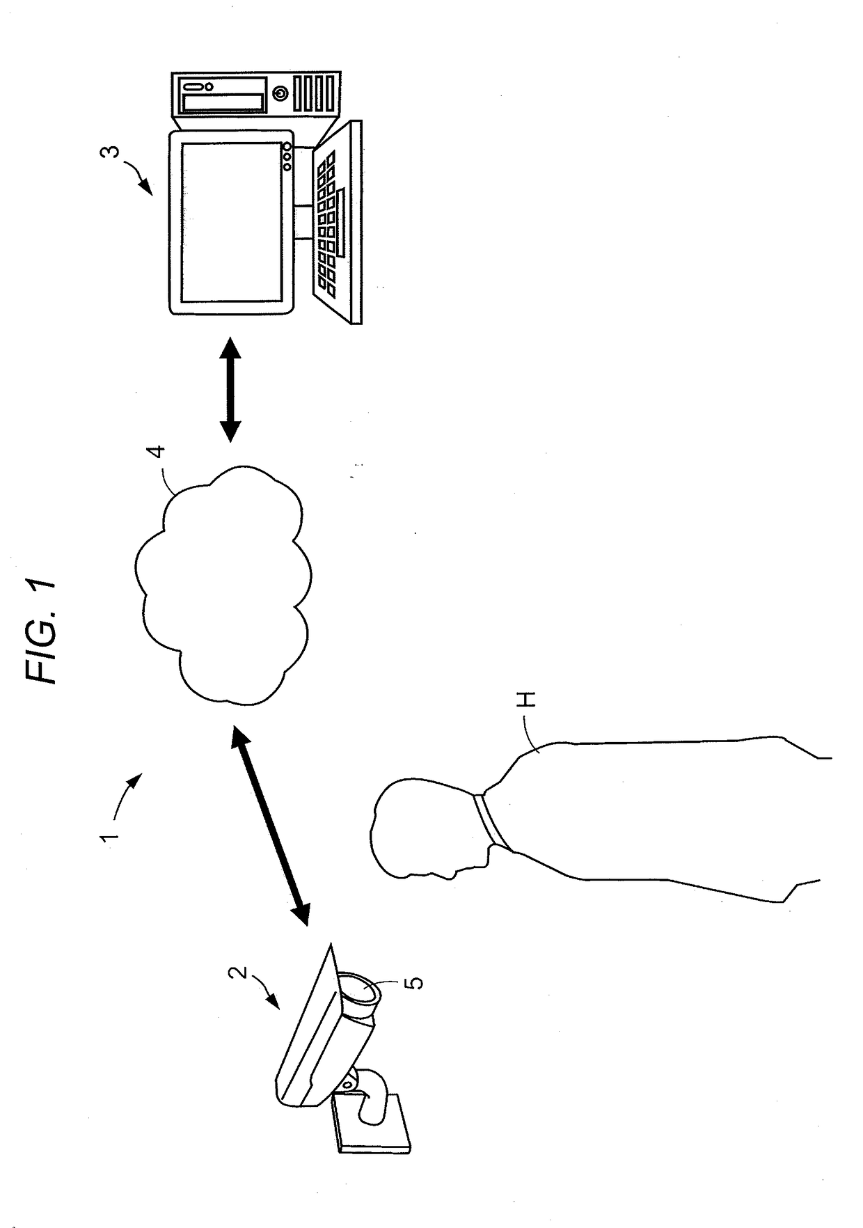
[0048]Pulse estimation system 1 estimates a pulse of a human body from information (captured image) obtained without contact with the human body. As shown in FIG. 1, the pulse estimation system 1 includes camera 2 imaging at least a portion of human (subject) H as an object and pulse estimation device 3 estimating a pulse (pulse rate or pulse wave) of human H from a captured image obtained by imaging with camera 2. In addition, in pulse estimation system 1, camera 2 and pulse estimation device 3 are connected to each other via network 4 such as the Internet...

second embodiment

[0072]FIG. 6 is a functional block diagram of pulse estimation system 1 of the second embodiment of the present disclosure. FIGS. 7A and 7B are explanatory diagrams of the pulse extracting process executed by a pulse calculator 23 of pulse estimation device 3. FIGS. 8A and 8B are explanatory diagrams illustrating a modification example of the pulse determining process shown in FIGS. 7A and 7B. In FIG. 6 to FIG. 8B, the same configuration elements as those of the above described first embodiment are denoted by the same reference marks. In addition, in the second embodiment, the matters especially not stated in the following are the same as the case of the above described first embodiment.

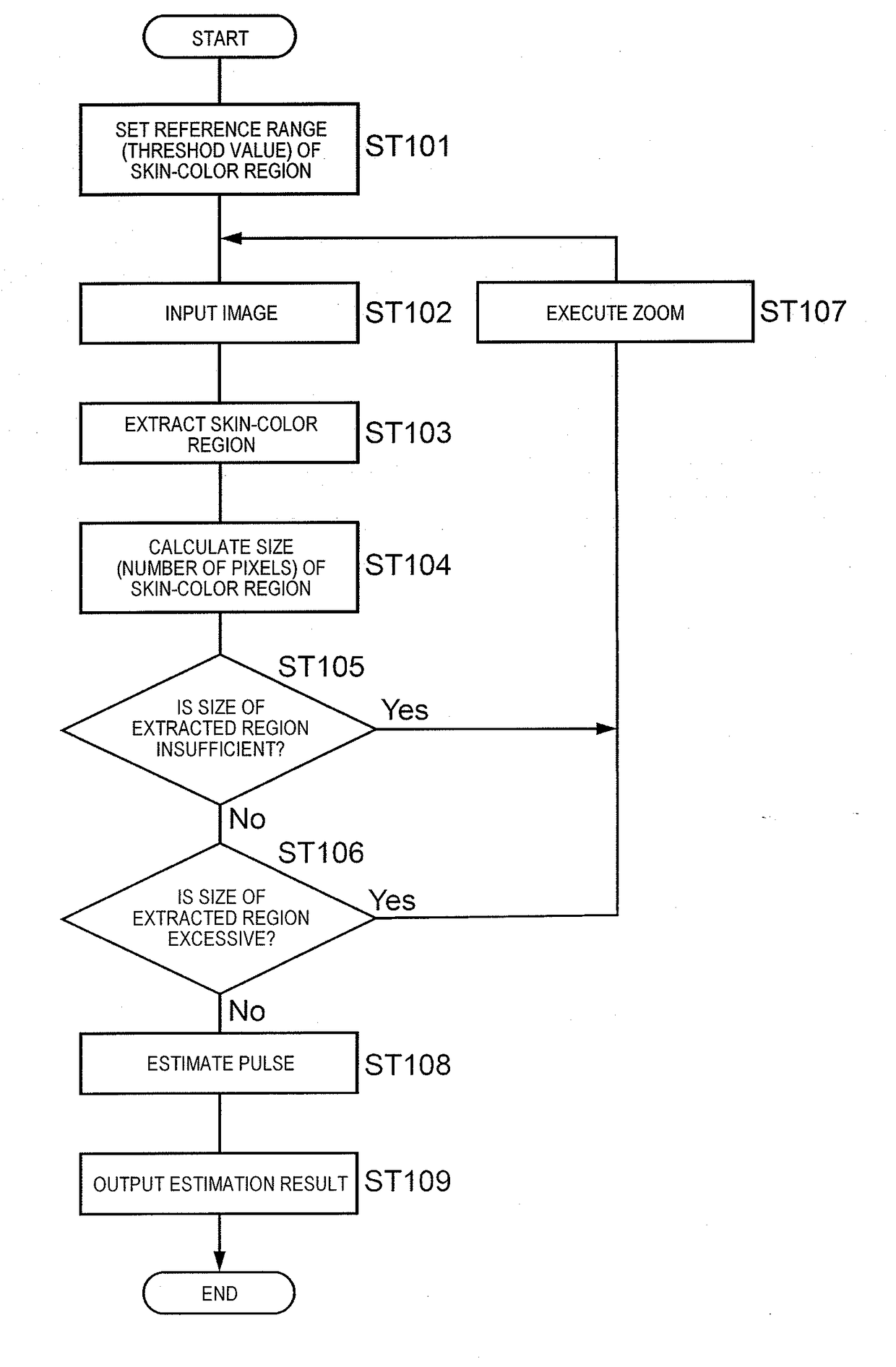
[0073]Since pulse estimation system 1 of the second embodiment determines whether or not adjustment of the size of the skin-color region extracted by region extractor 22 is necessary, pulse estimation system 1 is different from the case of the first embodiment, in view of performing the determination...

third embodiment

[0081]FIG. 10 is a functional block diagram of pulse estimation system 1 of the third embodiment of the present disclosure. FIGS. 11A and 11B are explanatory diagrams illustrating examples of an operation instruction of zoom commander 28 of pulse estimation device 3 shown in FIG. 10. In FIG. 10 and FIGS. 11A and 11B, the same configuration elements as those of the above described first or second embodiment are denoted by the same reference marks. In addition, in the third embodiment, the matters especially not stated in the following are the same as the case of the above described first or second embodiment.

[0082]Pulse estimation system 1 of the third embodiment is different from the case of the first embodiment, in view of transmitting the zoom command to a user of pulse estimation device 3 by zoom commander 28 instead of transmitting the zoom command to camera 2.

[0083]For example, in a case where region determiner 26 determines that the number of pixels of the skin-color region is...


PUM


Abstract

A pulse can be stably estimated based on an image data suitable for extracting a pulse signal. A pulse estimation device includes image input portion (21) to which time-sequential captured images including at least a portion of subject H as an object are input from camera (2); region extractor (22) that extracts a skin-color region from each of the captured images; zoom commander (28) that transmits a zoom command to camera (2) that has imaged the captured images or a user of camera (2) in order to adjust a size of the skin-color region; and pulse estimator (23) that estimates a pulse of subject H based on the skin-color region of the captured images obtained by imaging with camera (2), after the zoom command is transmitted.

Description

TECHNICAL FIELD[0001]The present disclosure relates to a pulse estimation device, a pulse estimation system, and a pulse estimation method which estimate a pulse of a human body from information obtained without contact with the human body.BACKGROUND ART[0002]In the related art, for measuring a pulse of a human, a method in which a measurer (such as a nurse) manually checks a pulsation by contacting a wrist of a subject with a finger, a method in which a dedicated measuring equipment is attached to a wrist, a finger, or the like of a subject so as to automatically detect the pulsation, and the like are known. On the other hand, in these measuring method, free behavior of a subject is temporarily restricted or there is need to attach measuring equipment on a subject. Therefore, a technology for estimating (detecting) a pulse without contact with a subject (human body) is developed.[0003]For example, in a technology of detecting a heart rate (in general, equivalent to a pulse rate) wi...

Claims


Application Information

Patent Timeline
Patent Type & Authority Applications(United States)
IPC IPC(8): A61B5/024H04N5/232G06T7/11G06T7/174
CPCA61B5/02427H04N5/23296H04N5/232127H04N5/232939G06T7/11G06T7/174G06T2207/10016G06T2207/10024G06T2207/30004A61B2562/0233A61B2576/00A61B5/0077A61B5/02416A61B5/1032A61B5/7485G06T7/0016G06T2207/30076G06T2207/30201H04N23/69H04N23/633H04N23/675
Inventor TEZUKA, TADANORINAKAMURA, TSUYOSHIMATSUO, MASATOSHI
Owner PANASONIC INTELLECTUAL PROPERTY MANAGEMENT CO LTD
Why Eureka
Try Eureka