Wheel lifting device

a technology for lifting devices and wheels, which is applied in the direction of hand carts, tyre parts, tyre repairs, etc., can solve the problems of requiring a great storage space, a large device, and a comparatively complicated all-in-one lifting device, and achieves the effect of improving the lifting devi

Active Publication Date: 2018-11-08
KOMPOSITPRODR VIKMANSHYTTAN
View PDF0 Cites 17 Cited by
  • Summary
  • Abstract
  • Description
  • Claims
  • Application Information

AI Technical Summary

Benefits of technology

[0005]An object of the present invention is to provide an enhan...

Problems solved by technology

All these known lifting devices are comparatively complicated and comprise a large number of c...

Method used


Image

  • Wheel lifting device
  • Wheel lifting device
  • Wheel lifting device

Examples


example

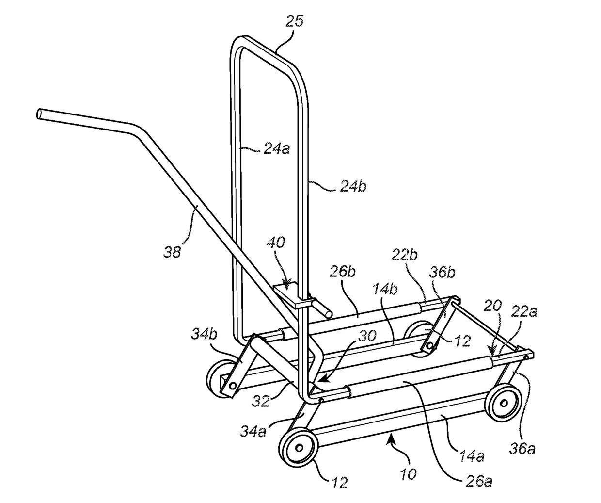
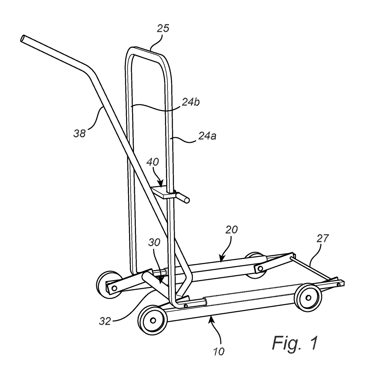
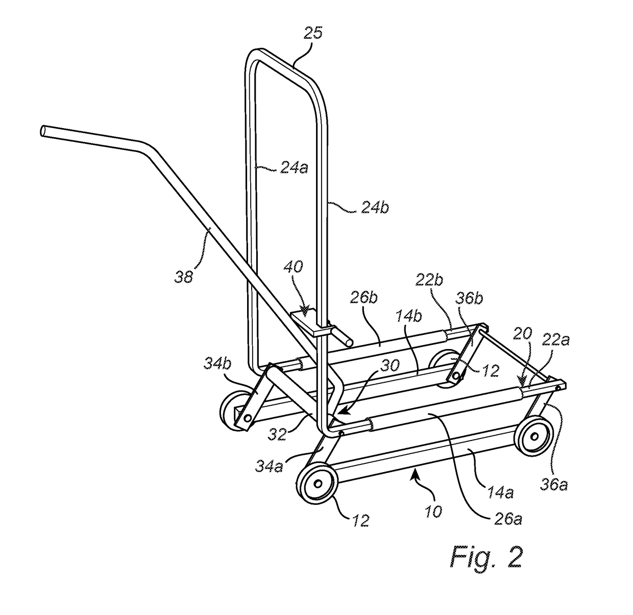
[0049]In the following and with reference to FIG. 5a, the conditions needed to be fulfilled for the blocking device 40 to prevent the lifting frame 20 from being lowered once the desired position has been reached and the manoeuvring lever 38 released is discussed. When the operator has raised the lifting frame 20 to the desired position and let go of the manoeuvring lever 30, the weight of the lifted wheel and the lifting frame 20 will influence the blocking device 40 by the force F. The vertical leg 24a having square cross section is received with a small clearance in the U-shaped recess 44 having opposing edges 44a, 44b. An edge pressure is thereby created between the blocking device 40 and the vertical leg 24a. The force A acting on the vertical leg is by reasons of equilibrium equal at both opposing sides of the vertical leg 24a. By friction between the blocking device 40 and the vertical leg, frictional forces μA are created.

[0050]The torque about centre axis M is:

Fy−2Ax / 2=0=>A...


PUM


Abstract

A wheel lifting device comprising a base structure with support means for being supported by a ground surface and a lifting frame with at least one wheel support member and a frame leg which extends upwardly at an angle to the ground surface. A link mechanism is connected to the base structure and to the lifting frame and a pivotal manoeuvring lever is connected to the link mechanism for lifting the lifting frame relative to the base structure. The blocking device for locking the manoeuvring lever at any desired pivotal position comprises a weight which is slidable along the frame leg and arranged to intersect the pivotal movement path of the manoeuvring lever and to be brought into frictional engagement with the frame leg when influenced by a force generated by the manoeuvring lever in order to block the lifting frame from downward movement relative to the base structure.

Description

TECHNICAL FIELD[0001]The invention concerns a device for lifting and positioning a wheel during wheel shifting on a vehicle, such as a car, a pick-up or the like.BACKGROUND[0002]Shifting wheels of a vehicle, e.g. shifting from summer to winter wheels and vice versa, may be cumbersome and involves heavy lifting and manipulation of the wheels. Typically, each wheel to be mounted needs to be lifted between 50-100 mm above the ground and then manipulated and positioned such that the mounting holes of the rim are aligned with the wheel hub. Thereafter, the wheel needs to be maintained in position while fastening the mounting screws or nuts. Especially at larger vehicles such as pick-up trucks, SUVs, cross country trucks, general purpose vehicles, jeeps and the like, where the wheels often are comparatively large and heavy, such lifting and handling of the wheels involves awkward working positions, is tiresome and may even lead to injuries to the person involved.PRIOR ART[0003]For this re...

Claims


Application Information

Patent Timeline
IPC IPC(8): B60B29/00B62B3/06
CPCB62B2203/10B62B2202/031B60B2340/36B62B3/0631B60B29/002B60B29/001B60B30/02B60B30/06B60B30/10B62B3/0606B62B2206/06
Inventor LINDGREN, MATS
Owner KOMPOSITPRODR VIKMANSHYTTAN
Why Eureka
Try Eureka