
Vehicle safety braking system

a technology for safety braking and vehicles, applied in the direction of abs control systems, automatic initiations, brake action initiations, etc., can solve the problems of serious injury to a person hit, damage to property, and/or one or more of several types of accidents

Inactive Publication Date: 2018-11-08
VISION TECH (GRP) LTD
View PDF14 Cites 2 Cited by
  • Summary
  • Abstract
  • Description
  • Claims
  • Application Information

AI Technical Summary

Benefits of technology

This patent aims to provide a device, system, vehicle or method that addresses the issue of accidents caused by vehicles moving without a driver present. The technical effect of this patent is to prevent accidents and ensure safety by reducing the number of accidents caused by drivers not engaging their braking system before exiting the vehicle. This may be achieved by providing a device, system, vehicle or method that prevents this issue in at least some circumstances.

Problems solved by technology

This movement without the driver present in the vehicle, know as a “roll-away”, may cause one or more of several types of accident.
Firstly, the vehicle may become damaged if it hits an obstacle or runs off a road.
Secondly, the vehicle may cause damage to property and / or serious injury to a person hit by the vehicle.
Thirdly, the driver may attempt to re-enter the moving vehicle in order to regain control of the vehicle and in doing so suffer serious injury, for example if the driver falls under the wheels of the vehicle during the attempt to re-enter the vehicle.
These accidents may be more serious when the vehicle is a relatively large and relatively heavy vehicle, for example a large commercial vehicle of the types described above.
Such vehicles when moving uncontrollably are liable to cause very serious damage to the vehicle itself and to property hit by the vehicle and / or cause very serious or fatal injury to persons hit by the vehicle or to a driver attempting to re-enter the vehicle.

Method used


Image

  • Vehicle safety braking system
  • Vehicle safety braking system
  • Vehicle safety braking system

Examples


Embodiment Construction

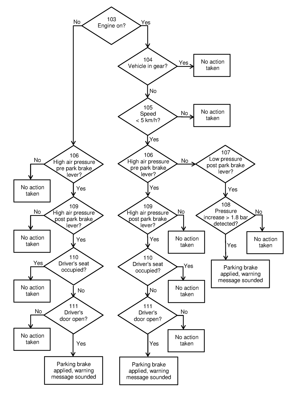
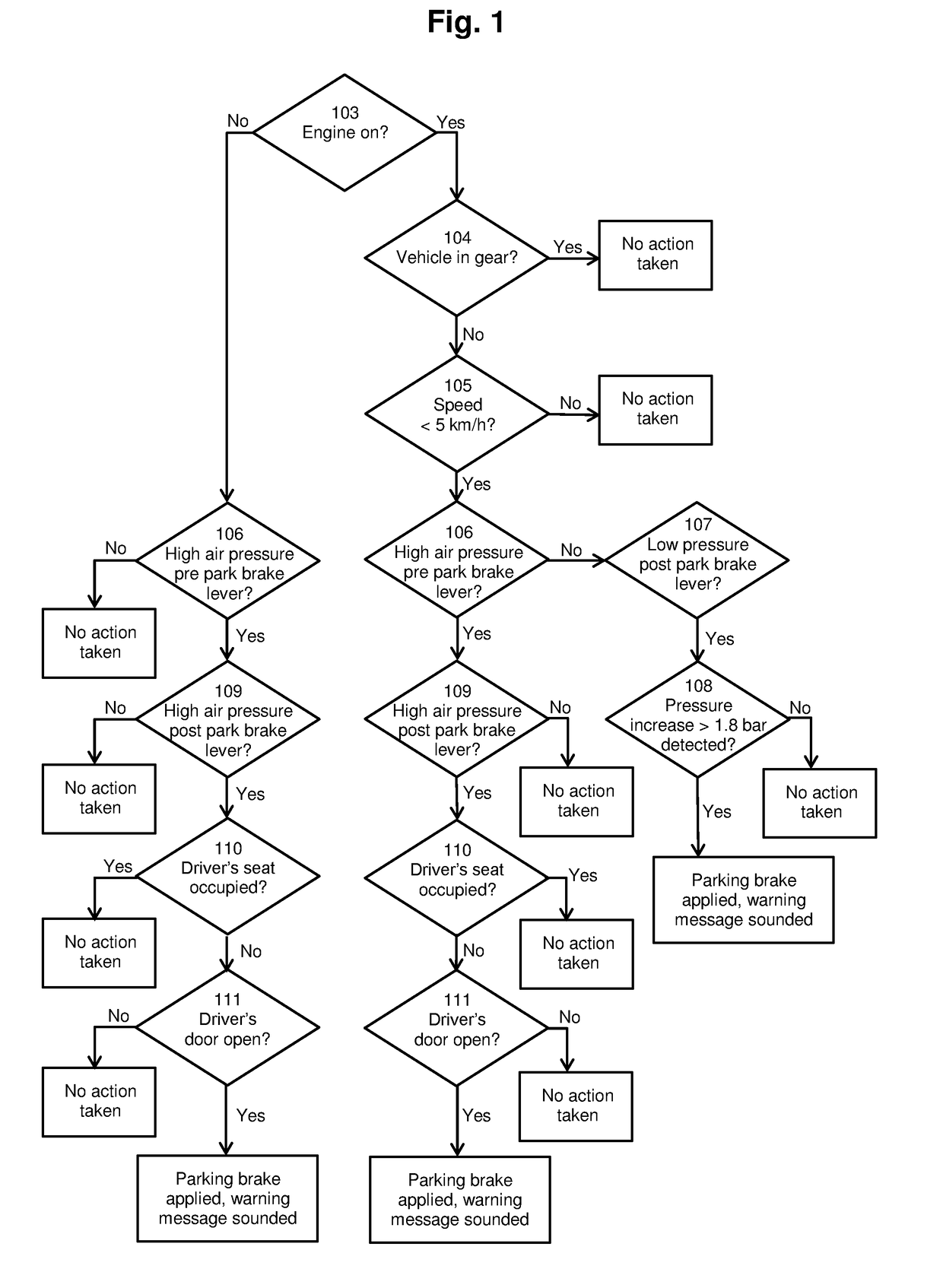
[0193]FIG. 1 shows a decision tree which illustrates the function of the device, system, vehicle and method of the present invention. This decision tree is implemented by an appropriate arrangement of electronic circuitry in a control module of the device, system or vehicle. A skilled person with knowledge of the decision tree of FIG. 1 would be able to implement this decision tree using known electronic components and arrangements. Each decision (enclosed in a diamond shape in FIG. 1) is made by a control module of the device using electronic sensor inputs and the illustrated combination of YES and NO answers produces either a decision by the device to take no action (outcome 101) or a decision to apply a parking brake in the vehicle and sound a warning message (outcome 102).

[0194]The decision process is carried out by the device or method of the present invention as follows when the device or system is fitted to a vehicle with an engine, a gear system, an air brake system arranged...


PUM


Abstract

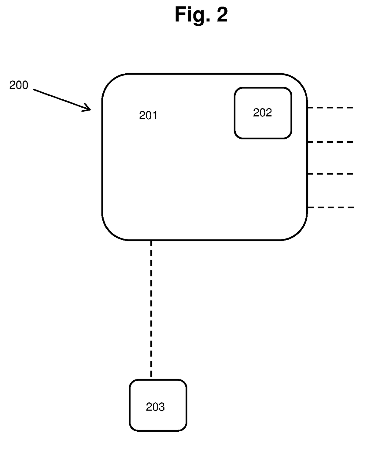
A vehicle safety device (200) for preventing an unoccupied vehicle moving uncontrollably. The device comprises a control module (201) and a brake module (203). The device (200) is configured to detect when a driver leaves said vehicle. The device (200) is also configured to activate, through the brake module (203), a braking system when the device detects that said driver has left the vehicle. The device may improve the safety of a vehicle in which it is fitted. A system (300) comprising the device (200) and a vehicle (400) comprising the system (300) are also described. A method of preventing an unoccupied vehicle moving is also described. The device, system, vehicle and method are particularly useful for preventing accidents in large commercial vehicles caused by a driver leaving the vehicle without engaging a parking brake.

Description

FIELD[0001]The present invention relates to a device, system or method for preventing a vehicle moving without a driver present in said vehicle. The present invention also relates to a vehicle comprising such a device and / or system, for example a large commercial vehicle. In particular the invention relates to a device, system or method for automatically applying a braking system of a vehicle, for example a large commercial vehicle, to prevent said vehicle moving, for example on an inclined surface, without a driver present in said vehicle.BACKGROUND[0002]Known vehicles, for example motor vehicles, comprise a parking brake which is used to prevent the vehicle from moving when it has stopped, for example when parked. If the parking brake (also known as a hand brake) is not engaged, it is possible for a vehicle parked on an inclined surface, for example a road with a gradient greater than 0%, to move under its own weight. In known vehicles, the parking brake has to be applied manually...

Claims


Application Information

Patent Timeline
IPC IPC(8): B60T7/12B60T7/14
CPCB60T7/122B60T7/14B60T2201/03B60T2220/00B60T2270/10B60T2270/88B60K28/04B60W2520/10B60W2510/186B60W2510/101B60W2510/0638
Inventor ARMSTRONG, NIGEL
Owner VISION TECH (GRP) LTD
Learn More