
Apparatus for preventing the rapid reloading of a semi-automatic firearm

a semi-automatic firearm and automatic reloading technology, applied in the field of semi-automatic firearms, can solve the problem that the firearm magazine cannot be easily removed from the firearm lower assembly, and achieve the effect of facilitating engagemen

Active Publication Date: 2018-11-08
QUINN DEAN FRANCIS +1
View PDF0 Cites 5 Cited by
  • Summary
  • Abstract
  • Description
  • Claims
  • Application Information

AI Technical Summary

Benefits of technology

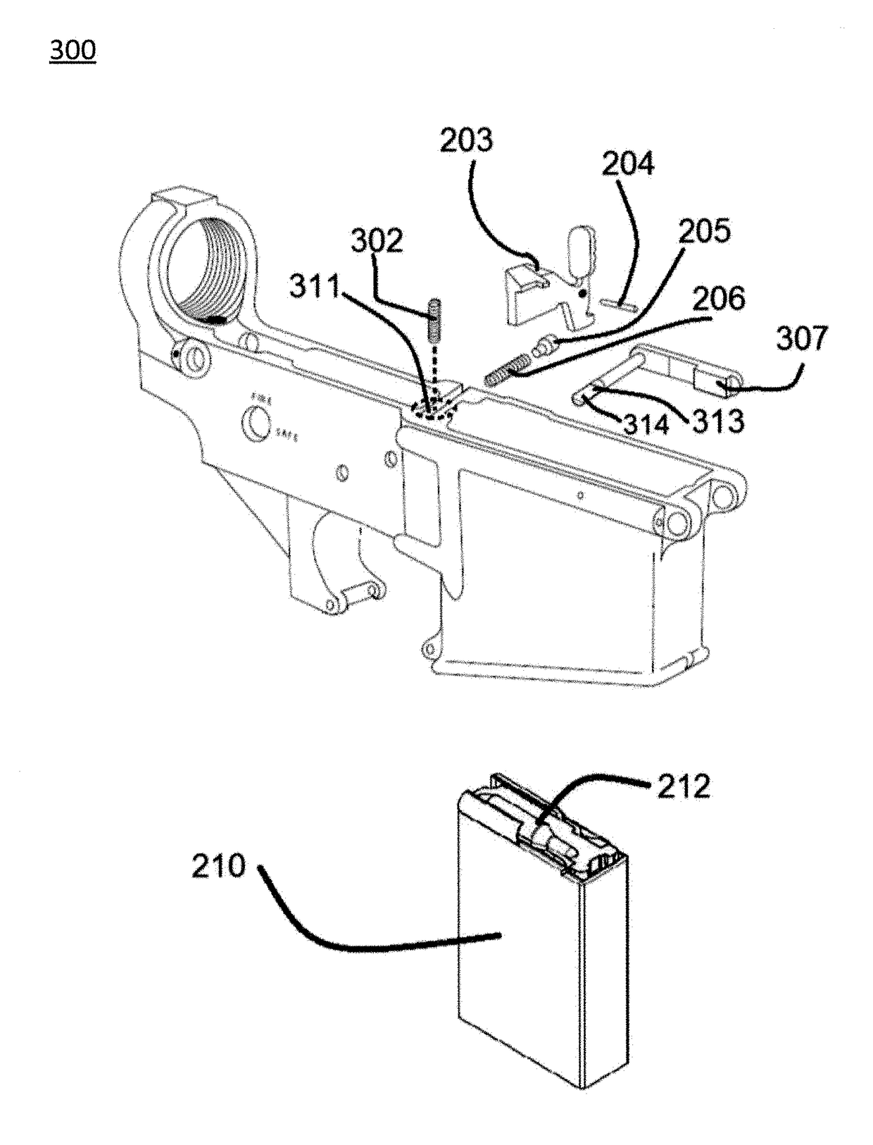
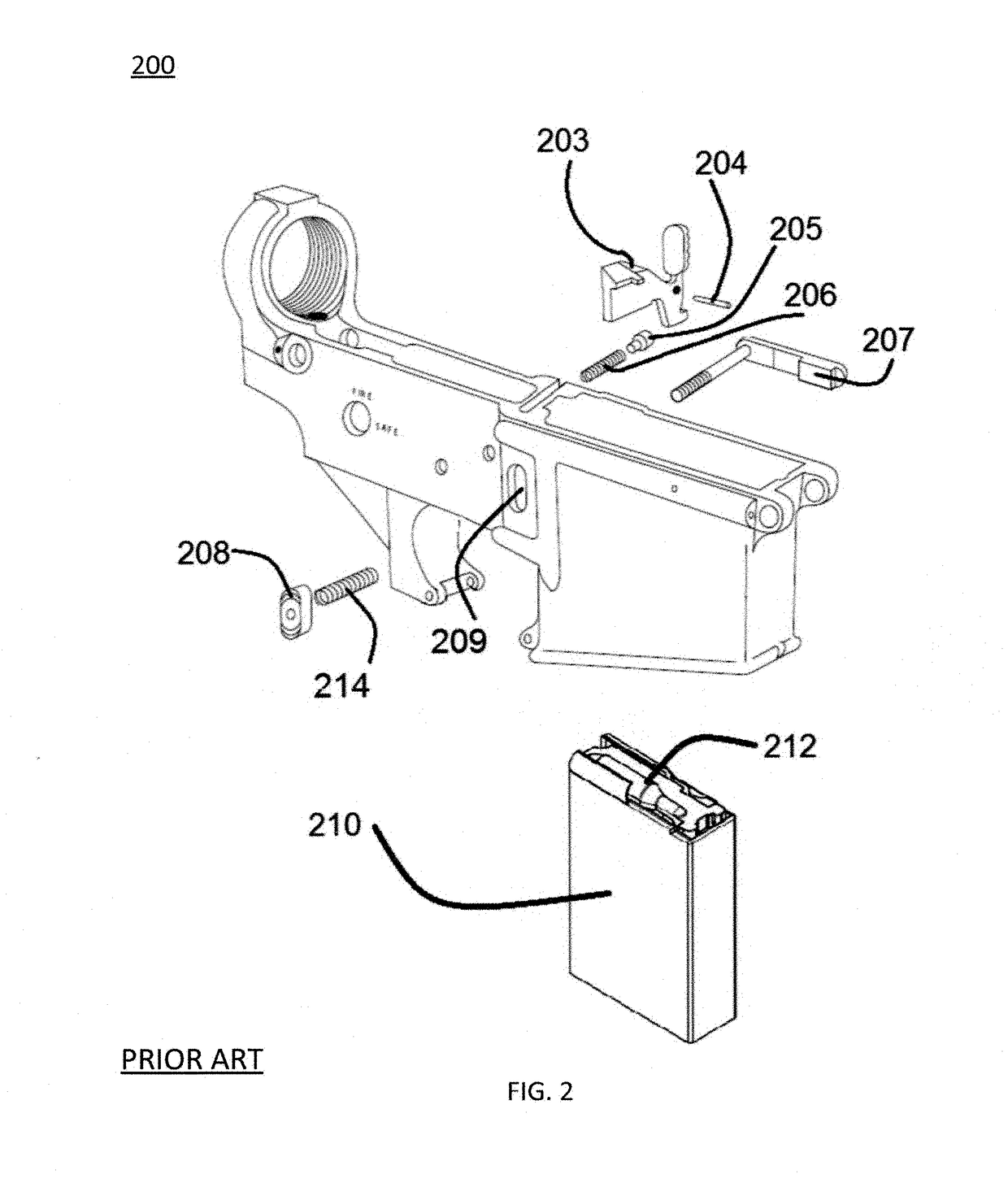
This patent describes a method and apparatus for converting a firearm with a readily detachable firearm magazine into a firearm with a non-detachable firearm magazine. The conversion involves replacing the functional magazine position button with a dummy or non-functional button, removing the retaining device that secures the firearm magazine lock, and replacing the magazine lock with a modified version that can be secured by the retaining device. The firearm can also have an indicator to show the number of rounds of ammunition present in the magazine. The purpose of the invention is to improve firearm safety and prevent accidental detachment of the firearm magazine.

Problems solved by technology

Further, such an apparatus requires removal of a retaining device that secures a firearm magazine lock wherein the retaining device is inaccessible without at least partial removal of the firearm upper assembly from the firearm lower assembly.
The firearm magazine and the firearm lower assembly may be made from a resilient material such as a metal or a high impact polymer and the firearm magazine is not easily removed from the firearm lower assembly.

Method used


Image

  • Apparatus for preventing the rapid reloading of a semi-automatic firearm
  • Apparatus for preventing the rapid reloading of a semi-automatic firearm
  • Apparatus for preventing the rapid reloading of a semi-automatic firearm

Examples


Embodiment Construction

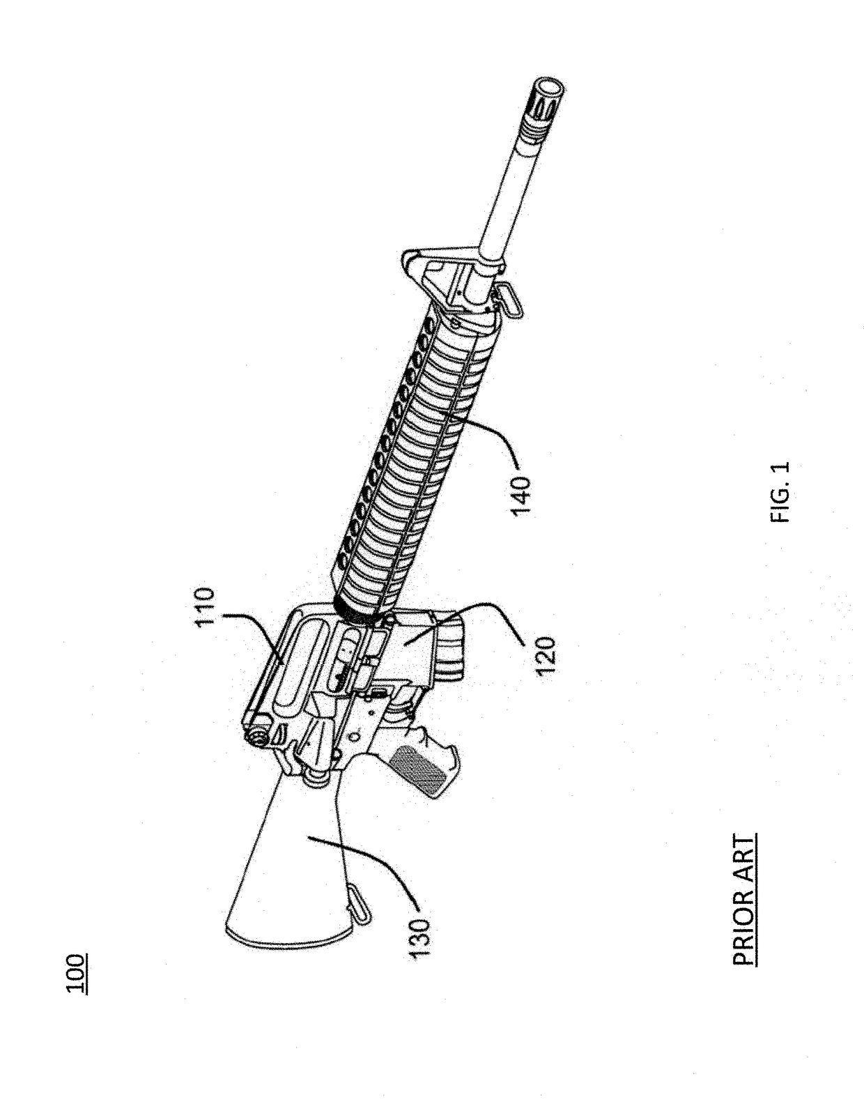
[0022]The following description is presented to enable a person skilled in the art to make and / or use the invention. Various modifications to the described embodiments herein will be readily apparent to those skilled in the art and the generic principles can be applied to other embodiments. Thus, the present invention is not intended to be limited to the embodiments and examples shown herein but is to be given its widest possible scope in accordance with the features and principles shown and described herein. The particular features and advantages of the invention will become more apparent with reference to the appended figures, taken in conjunction with the following description.

[0023]As used herein when referring to firearm magazines, “readily detachable” means removable or exchangeable from a firearm without any significant firearm disassembly, such as having to remove or partially remove an firearm upper assembly from a firearm lower assembly. “Non-readily detachable” or “not re...


PUM


Abstract

A firearm apparatus is described comprising a firearm upper assembly and a firearm lower assembly, the firearm lower assembly comprising a firearm magazine container, wherein swapping of or refilling of a firearm magazine that is resident within the magazine container necessitates at least partial removal of the firearm upper assembly or may require complete removal of the firearm upper assembly from the firearm lower assembly. Further, such an apparatus requires removal of a firearm magazine retaining device that secures a firearm magazine lock wherein the retaining device is inaccessible without the at least partial removal of the firearm upper assembly from the firearm lower assembly. The firearm lower assembly may have a firearm magazine container that has a closed or partially closed bottom end to prevent switching out of a firearm magazine and the firearm lower assembly may have an opening in the top end sized for receiving a firearm magazine. A new firearm lower assembly is described that has no magazine position button as well as a conversion kit and a method of using a conversion kit to convert a semi-automatic firearm with a readily detachable firearm magazine into a firearm having a non-readily detachable firearm magazine.

Description

CROSS-REFERENCE TO RELATED APPLICATIONS[0001]This application claims the priority benefit of U.S. provisional patent application Ser. No. 62 / 344,975 for “An Apparatus For Preventing The Rapid Reloading Of A Semi-Automatic Firearm” by Dean F. Quinn, et al., filed Jun. 2, 2016, the entire disclosure of which is incorporated herein by reference.FIELD OF THE INVENTION[0002]The present invention relates in general to semi-automatic firearms. More specifically, the present invention relates to a novel semi-automatic firearm that cannot be rapidly reloaded, a kit for converting an existing semi-automatic firearm with a readily detachable firearm magazine into a firearm that has a non-readily detachable firearm magazine, and a method for this conversion.BACKGROUND[0003]The United States has gun laws that regulate the sale, possession, and use of firearms and ammunition. Federal gun laws along with most States and some local jurisdictions have additionally imposed their own firearms restrict...

Claims


Application Information

Patent Timeline
IPC IPC(8): F41A17/38
CPCF41A17/38
Inventor QUINN, DEAN FRANCISWATT, DANIEL CLAUDE
Owner QUINN DEAN FRANCIS
Learn More