Eureka AIR delivers breakthrough ideas for toughest innovation challenges, trusted by R&D personnel around the world.

Method and System for Identifying Energy Consumption of Electrical Appliance

a technology for electrical appliances and energy consumption, applied in the integration of power network operation systems, ac network voltage adjustment, instruments, etc., can solve the problems of large high cost of professional manpower, and significant increase in energy consumption, so as to improve the safety and reliability of the use of electrical appliances.

Active Publication Date: 2018-11-08
DELIGHT INNOVATIVE TECH LTD
View PDF0 Cites 0 Cited by
  • Summary
  • Abstract
  • Description
  • Claims
  • Application Information

AI Technical Summary

Benefits of technology

This invention relates to a method and system for monitoring and identifying the energy consumption of electrical appliances. A string current controller is used to control the power of terminal controllers in a string group which are connected to a group of electrical appliances. The controller detects and records the power value of each terminal controller in real-time and compares it with the rated power of the controller. This allows the power of each terminal controller to be monitored and identified in real-time, thus improving safety and reliability in the use of electrical appliances. Additionally, the invention suggests a method to prioritize the removal of terminal controllers based on their priority level, which helps to reduce energy consumption and improve overall performance.

Problems solved by technology

However, unfortunately, the use of a large number of electrical appliances has led to a significant increase in energy consumption, at the same time, it has not been able to know which electrical appliances are mainly responsible for the large increase in energy consumption, and at what time period the large increase in energy consumption is caused.
Therefore, it requires expensive professional manpower and takes a lot of manpower and capital costs to replace the arrangement of energy-saving appliances.

Method used


Image

  • Method and System for Identifying Energy Consumption of Electrical Appliance
  • Method and System for Identifying Energy Consumption of Electrical Appliance
  • Method and System for Identifying Energy Consumption of Electrical Appliance

Examples


Embodiment Construction

[0033]The present invention will be described below with reference to the accompanying drawings.

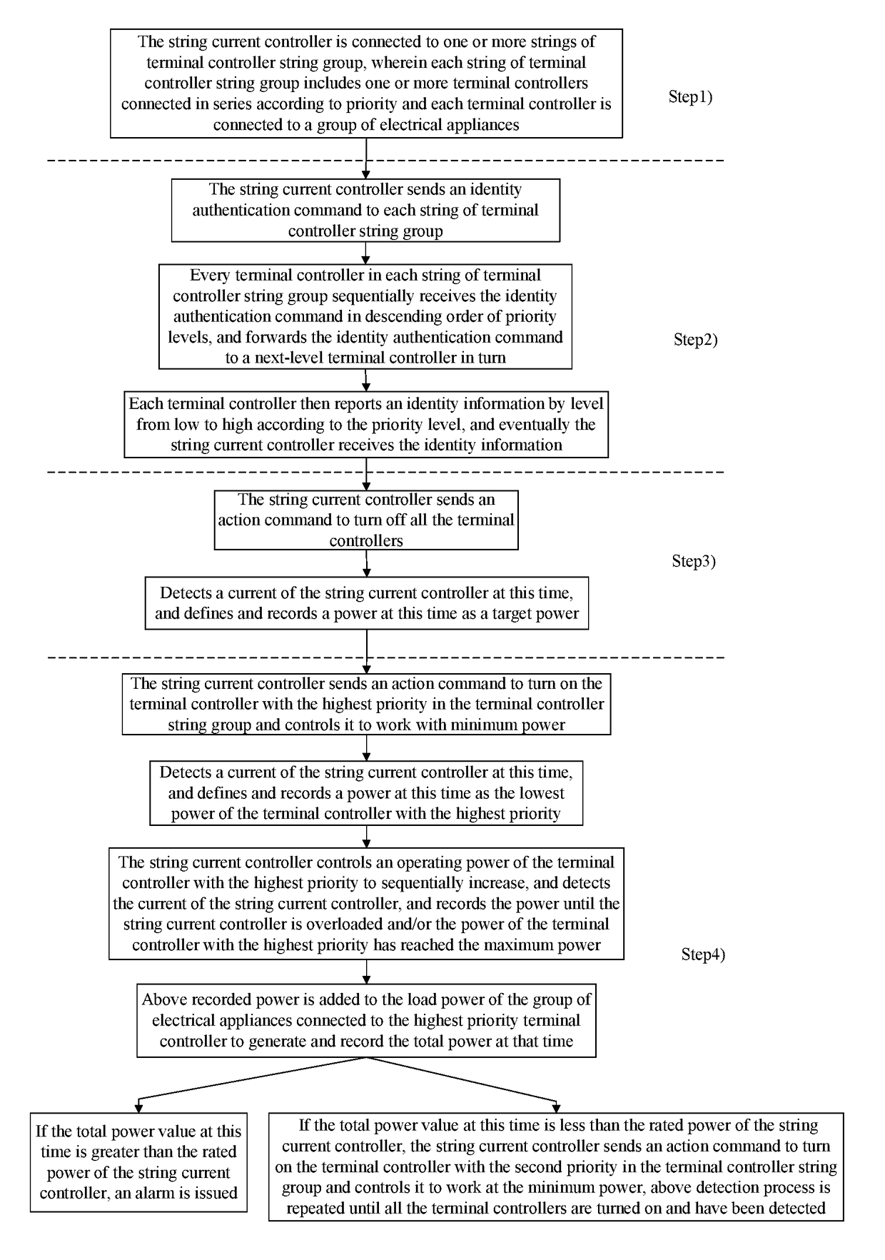
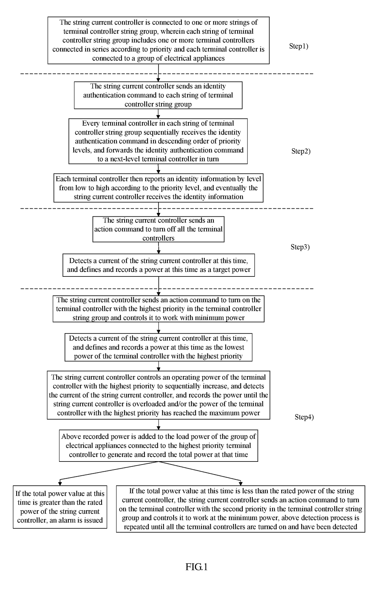
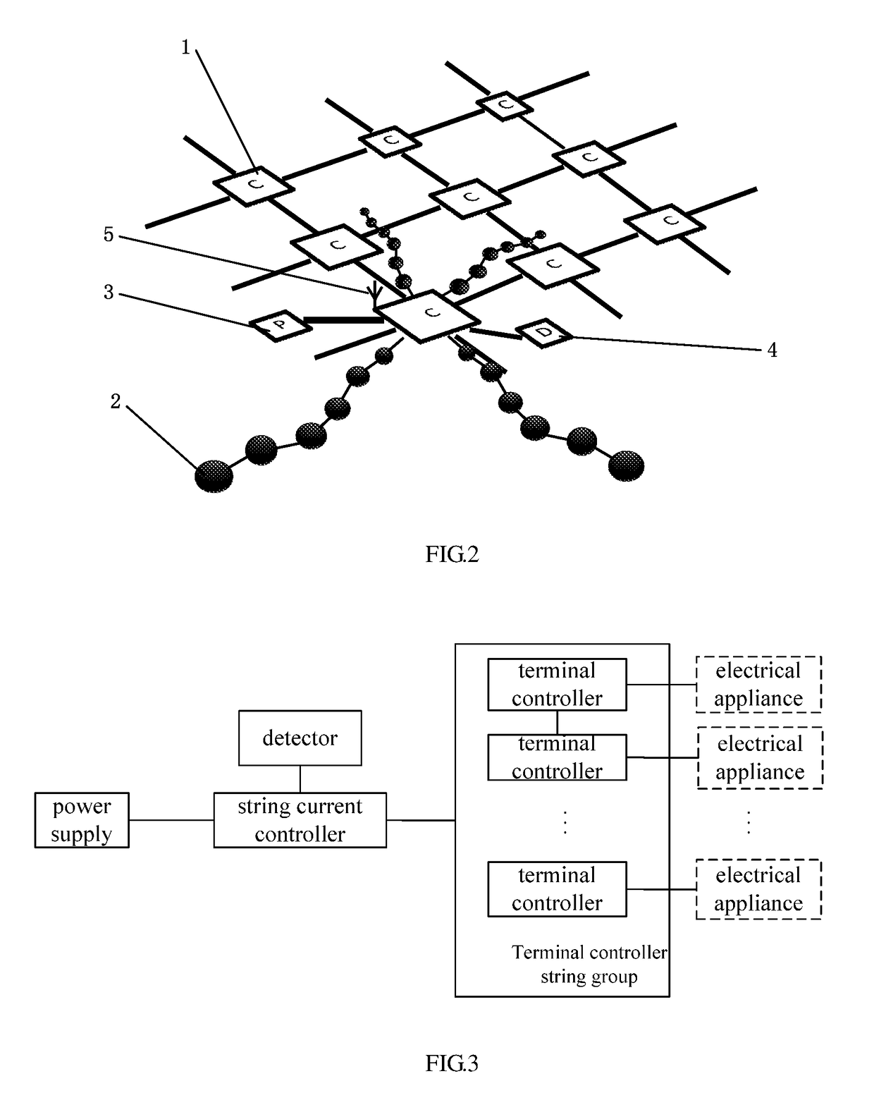
[0034]FIG. 1 is a flow chart of a method for identifying energy consumption of electrical appliances according to the present invention, FIG. 2 is a schematic structural diagram of identification of energy consumption of electrical appliances in for example a practical application, as shown in FIG. 1, the following steps are included:

[0035]1) A string current controller is used to connect one or more strings of terminal controller string group, wherein each string of terminal controller string group includes one or more terminal controllers connected in series according to priority and each terminal controller is connected to a group of electrical appliances; and wherein the string current controller used may be hardware devices such as a central controller etc.;

[0036]2) The string current controller sends an identity authentication command to each string of terminal controller string gro...


PUM


Abstract

The present invention relates to a method and a system for identifying energy consumption of electrical appliances. The method uses a string current controller to connect one or more strings of terminal controller string group, wherein each string of terminal controller string group includes one or more terminal controllers connected in series according to priority and each terminal controller is connected to a group of electrical appliances, the string current controller controls, via commands, the power of every terminal controller that are turned on in order of priority in the terminal controller string group, and detects and records the power value, and compares the power value with the rated power of the string current controller, thus, the power of each terminal controller can be monitored and identified in real time to identify and alarm the energy consumption, thereby improving the safety and reliability of the use of electrical appliances.

Description

TECHNICAL FIELD[0001]The present invention relates to the technical field of energy consumption monitoring, and in particular to a method and a system for identifying energy consumption of electrical appliances.BACKGROUND TECHNIQUE[0002]At present, the use of electrical appliances, especially indoor appliances, has become very popular. In particular, the installation and use of indoor lighting control systems (such as LED lighting control system) for rendering special scenes is particularly popular. However, unfortunately, the use of a large number of electrical appliances has led to a significant increase in energy consumption, at the same time, it has not been able to know which electrical appliances are mainly responsible for the large increase in energy consumption, and at what time period the large increase in energy consumption is caused. Therefore, it requires expensive professional manpower and takes a lot of manpower and capital costs to replace the arrangement of energy-sa...

Claims


Application Information

Patent Timeline
IPC IPC(8): G01R22/06G01R21/06
CPCG01R22/06G01R21/06G01R21/1336H02J2310/12H02J2310/14H02J13/00004H02J3/14Y04S20/222Y04S20/242Y02B70/30Y02B70/3225H02J13/00002
Inventor YAU, KIN HING
Owner DELIGHT INNOVATIVE TECH LTD
Why Eureka
Eureka Blog
Learn More