Cove lighting

a technology for cove lighting and cove lighting, applied in the field of cove lighting, can solve the problems of unnatural or unpleasant difficulty in non-experts in creating visually attractive illumination from cove lighting, and inability to meet the requirements of other components, and achieve the effect of reducing processing requirements or capabilities of other components

Active Publication Date: 2018-11-08
SIGNIFY HLDG BV
View PDF0 Cites 27 Cited by
  • Summary
  • Abstract
  • Description
  • Claims
  • Application Information

AI Technical Summary

Benefits of technology

[0008]Proposed concepts therefore include individually controlling or driving a plurality of consecutive light source modules or segments of cove lighting. A plurality of light source modules may therefore be brought together so as to form a single virtual cove lighting device, and the single virtual lighting device may be controlled using a single control unit / signal that is adapted to individually or separately control each of the light source modules in a coordinated manner so as to provide a single overall desired lighting output (that may replicate an outdoor lighting condition on a ceiling for example). Embodiments may therefore provide for modular cove lighting formed from a plurality of sub-modules (e.g. separate light sources) that provide for design and installation flexibility. For example, the sub-modules may be movable relative so each other so that their relative positioning and / or orientation may be adjusted according to requirements. Furthermore, the modular design may allow for sub-modules to be added and / or removed in order to modify the size, shape, light output capabilities, etc. of the cove lighting device.
[0039]Embodiments may further comprise: a server device comprising a cove lighting control system; and a client device comprising a display system. Dedicated data processing means may therefore be employed for the purpose of generating a lighting control signal, thus reducing processing requirements or capabilities of other components or devices of the system.

Problems solved by technology

However, the illumination from cove lighting can look un-natural or unpleasant, and the creation of visually attractive illumination from cove lighting can be expensive and / or challenging for non-experts.
If the cove lighting system is poorly designed, it may cause glare and provide non-uniform illumination of a ceiling.
It may also fail to provide the type or amount of light necessary to adequately illuminate the space.

Method used


Image

  • Cove lighting
  • Cove lighting
  • Cove lighting

Examples


Embodiment Construction

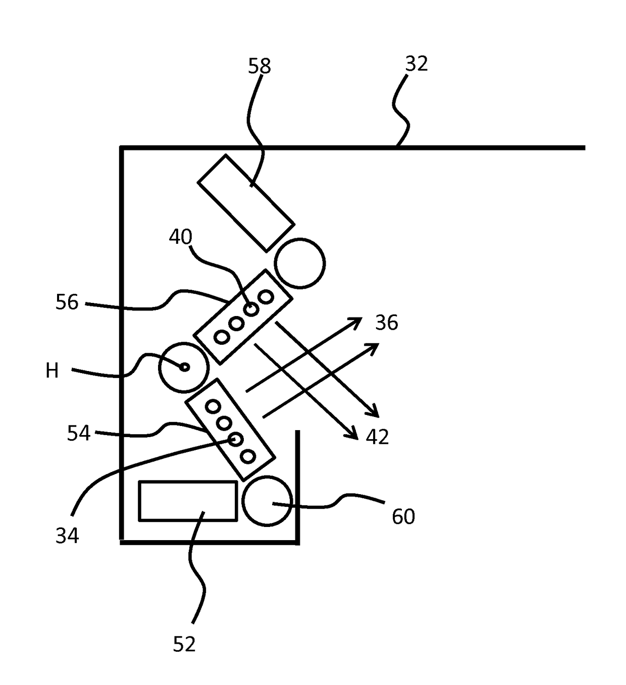
[0054]The illustrative embodiments provide concepts for controlling cove lighting systems. Based on a lighting control signal, primary light sources (for illuminating a ceiling) may be separately or individually controlled in order to illuminate a ceiling in a manner which mimics an outdoor lighting condition. Thus, proposed is the concept replicating an outdoor lighting condition by individually controlling each of a plurality of coving light sources of cove lighting. In the context of this disclosure, the term “cove lighting” may be used to refer to the light effect created or rendered by light sources, light source modules, light fixtures or elongated luminaires positioned in a cove or mounted on a wall, or may be used to refer to the light sources, light source modules, light fixtures or elongated luminaires themselves.

[0055]Illustrative embodiments may be utilized in many different types of coving lighting systems, such as elongated LED-based up-lighting systems or continuous l...


PUM


Abstract

Presented are concepts for controlling cove lighting. Once such concept provides cove lighting adapted to output decorative light for illuminating the ceiling of an architectural space. The cove lighting comprises a control unit adapted to individually control each of the primary light sources in response to a lighting control signal so that the output decorative light mimics an outdoor lighting condition.

Description

FIELD OF THE INVENTION[0001]This invention relates to the field of cove lighting and more particularly to controlling light output from cove lighting for illuminating a ceiling of an architectural space.BACKGROUND OF THE INVENTION[0002]Architectural spaces, such as rooms for example, are often illuminated by either natural light or by artificial light. It is known that illumination of a space can have an impact on how the space is perceived by person in or near the space. For instance, a room is typically perceived to be more spacious if its surfaces (such as walls and / or ceilings) are brightly illuminated. Spaces with well-illuminated walls and ceilings are also typically perceived to be more pleasant.[0003]Current lighting solutions typically illuminate the ceiling of a space using cove lighting (e.g. lighting positioned in a ceiling cove or mounted high up on a wall close to the ceiling). However, the illumination from cove lighting can look un-natural or unpleasant, and the crea...

Claims


Application Information

Patent Timeline
Patent Type & Authority Applications(United States)
IPC IPC(8): H05B33/08F21V21/005F21V23/04H05B44/00
CPCH05B33/0872F21V21/005F21V23/0442F21V23/0492F21Y2103/10F21Y2115/10F21W2121/008H05B47/155H05B47/11Y02B20/40H05B45/20
Inventor VAN DE SLUIS, BARTEL MARINUSDEKKER, TIMALIAKSEYEU, DZMITRY VIKTOROVICHNEWTON, PHILIP STEVEN
Owner SIGNIFY HLDG BV
Why Eureka
Try Eureka