Coating device and method of producing coated sheet

Inactive Publication Date: 2018-11-22
SUMITOMO ELECTRIC IND LTD +1
View PDF0 Cites 1 Cited by
  • Summary
  • Abstract
  • Description
  • Claims
  • Application Information

AI Technical Summary

Benefits of technology

The present invention provides a coating device and method that can apply ink with a low viscosity without compromising the quality of the ink. This allows for improved coating performance and efficiency.

Problems solved by technology

However, the exiting slot-type coater can be used for inks having physical properties in a narrow range, and it is difficult for the coater to perform coating with ink having a comparatively low viscosity of, for example, about several mPa·s.
However, because the gravure-type coater and the bar-type coater form an air-released liquid reservoir, the quality of ink tends to degrade.
To be specific, water in the air dissolves into ink in the liquid receiver pan to cause gelation of the ink, and therefore a defect in a coating film tends to occur.

Method used


Image

  • Coating device and method of producing coated sheet
  • Coating device and method of producing coated sheet
  • Coating device and method of producing coated sheet

Examples


first embodiment

[Coating Device]

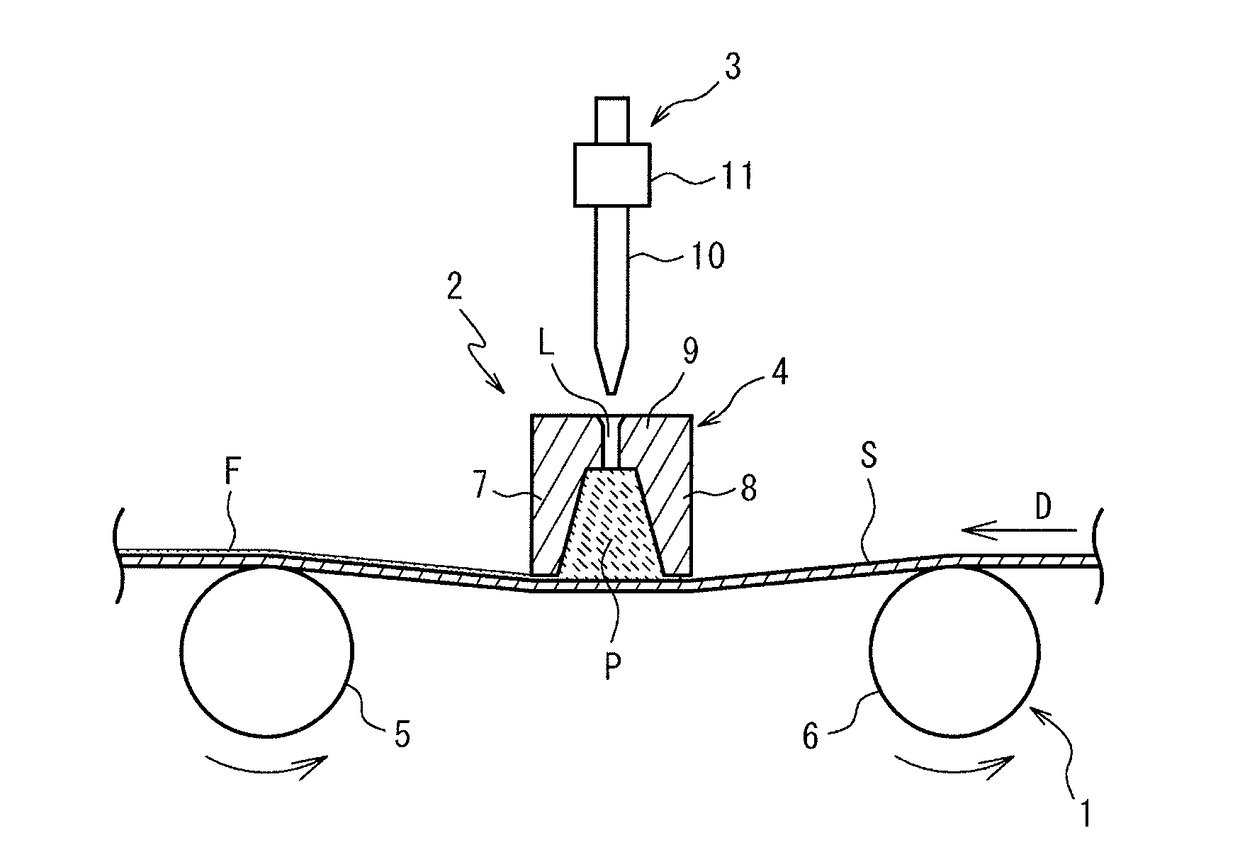
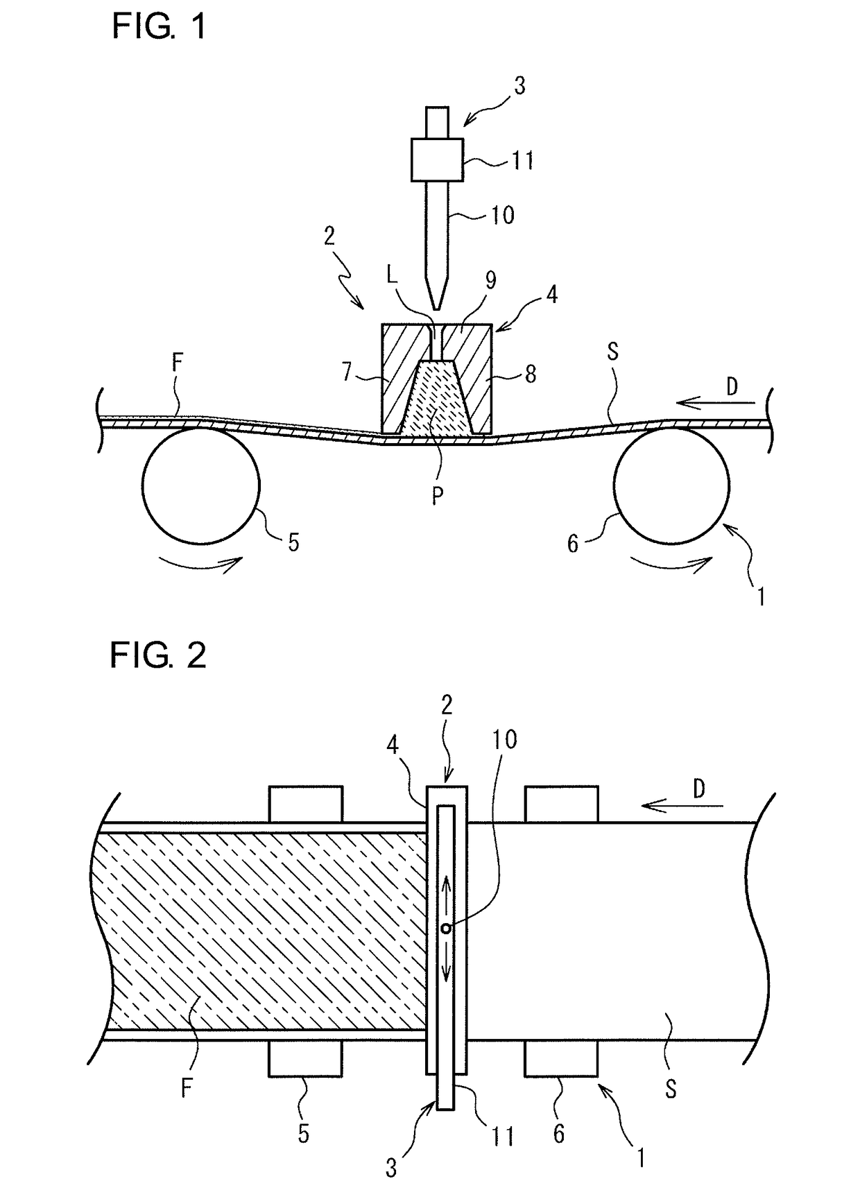
[0031]A coating device of FIGS. 1 and 2 mainly includes a module (travel module 1) that causes a strip-shaped sheet S to travel in a longitudinal direction, a module (coating module 2) that coats a surface of the strip-shaped sheet S with ink while the strip-shaped sheet S travels, and a module (supply module 3) that supplies the ink to the coating module 2. The coating device is used to form a coating film F of ink on the surface of the strip-shaped sheet S.

[0032]The coating module 2 includes a slot-type coating head 4 that is disposed above the strip-shaped sheet S so as to span the strip-shaped sheet S in the width direction. The slot-type coating head 4 includes an ink storage part P that widens toward the strip-shaped sheet S in cross-sectional view and an ink supply path L that communicates with an upper part of the ink storage part P.

[0033]The travel module 1 causes the strip-shaped sheet S to travel in the longitudinal direction, preferably, horizontally. In ...

second embodiment

Coating Device

[0084]A coating device of FIG. 4 mainly includes a module (travel module 1) that causes a strip-shaped sheet S to travel in a longitudinal direction, a module (coating module 2a) that coats a surface of the strip-shaped sheet S with ink while the strip-shaped sheet S travels, and a module (supply module 3) that supplies the ink to the coating module 2a.

[0085]The coating module 2a includes a slot-type coating head 4a that is disposed above the strip-shaped sheet S so as to span the strip-shaped sheet S in the width direction. The slot-type coating head 4a includes an ink storage part P that widens toward the strip-shaped sheet S in cross-sectional view and a slit-shaped ink supply path L that communicates with an upper part of the ink storage part P.

[0086]The travel module 1 and the supply module 3 of the coating device of FIG. 4 are the same as the travel module 1 and the supply module 3 of the coating device of FIG. 1. The ink used for coating and the strip-shaped sh...

third embodiment

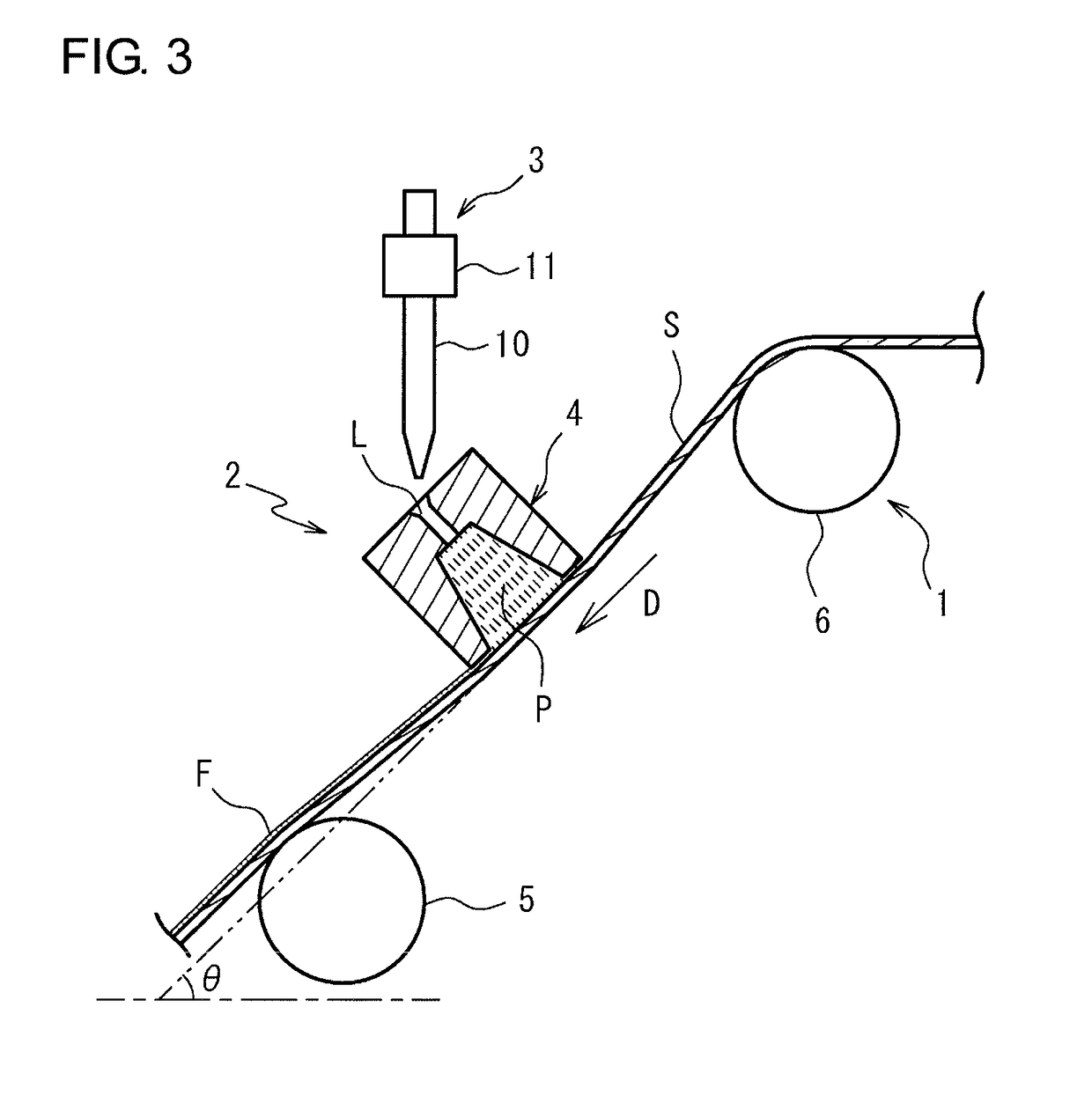
[0103]A coating device of FIG. 5 mainly includes a module (travel module 1) that causes a strip-shaped sheet S to travel in a longitudinal direction, a module (coating module 2b) that coats a surface of the strip-shaped sheet S with ink while the strip-shaped sheet S travels, and a module (supply module 3) that supplies the ink to the coating module 2b.

[0104]The coating module 2b includes a slot-type coating head 4b that is disposed above the strip-shaped sheet S so as to span the strip-shaped sheet S in the width direction. The slot-type coating head 4b includes an ink storage part P that widens toward the strip-shaped sheet in cross-sectional view and a slit-shaped ink supply path L that communicates with an upper part of the ink storage part P.

[0105]The travel module 1 of the coating device of FIG. 5 is the same as the travel module 1 of the coating device of FIG. 1. The supply module 3 of the coating device of FIG. 5 is the same as the supply module 3 of the coating device of F...


PUM

PropertyMeasurementUnit
Angleaaaaaaaaaa
Dispersion potentialaaaaaaaaaa
Widthaaaaaaaaaa

Abstract

A coating device according to an aspect of the present invention includes a travel module that causes a strip-shaped sheet to travel in a longitudinal direction, a coating module that coats a surface of the strip-shaped sheet with ink while the strip-shaped sheet travels, and a supply module that supplies the ink to the coating module. The coating module includes a slot-type coating head that is disposed above the strip-shaped sheet so as to span the strip-shaped sheet in a width direction. The slot-type coating head includes an ink storage part that widens toward the strip-shaped sheet in cross-sectional view and an ink supply path that communicates with an upper part of the ink storage part.

Description

TECHNICAL FIELD[0001]The present invention relates to a coating device and a method of producing a coated sheet. The present application claims priority over Japanese Patent Application No. 2015-227069, filed on Nov. 19, 2015, the entire contents of which are incorporated herein by reference.BACKGROUND ART[0002]For example, a process of producing an optical sheet or a flexible printed circuit board may include a step of coating an elongated sheet with ink. Examples of a known coating device (coater) used in the coating step include a slot-type coater that uses a die having an ink ejection slot, a gravure-type coater that uses a gravure roll that forms a thin film of ink on a surface thereof and transfers the ink to a sheet, and a bar-type coater that uses a bar-shaped member (doctor) that wipes off residual ink on a sheet surface.[0003]A general slot-type coater supplies ink to a die, and pushes the ink out of a slot in the die. Therefore, ink is not likely to contact air before the...

Claims


Application Information

Patent Timeline
IPC IPC(8): B05C5/02B05D1/26B05C11/10
CPCB05C5/0254B05D1/26B05C5/0208B05C11/10B05C1/0839B05C1/0869B05C3/18B05C11/023B05C11/025B05D2252/02
Inventor MIYATA, KAZUHIROKASUGA, TAKASHIOKA, YOSHIOOKUDA, YASUHIROPARK, JINJOOUEDA, HIROSHIOKAMOTO, KOHEI
Owner SUMITOMO ELECTRIC IND LTD
Why Eureka
Try Eureka