Indoor illumination lamp

a technology for indoor lighting and lamps, applied in the field of indoor illumination lamps, can solve problems such as foreign matter such as dust or dirt, and achieve the effect of narrowing or eliminating gaps and expanding the irradiation rang

Active Publication Date: 2018-11-22
YAZAKI CORP
View PDF1 Cites 2 Cited by
  • Summary
  • Abstract
  • Description
  • Claims
  • Application Information

AI Technical Summary

Benefits of technology

The present invention provides an indoor illumination lamp that can expand its lighting coverage and prevent foreign objects from entering through the light source opening. This is achieved through a design that narrows the gap between the substrate and the housing where the light source opening is located, making it difficult for foreign objects to enter. The inclined plane part at the light source opening also helps to expand the irradiation range. Overall, the indoor illumination lamp described in this patent offers expanded lighting coverage while minimizing the risk of foreign objects entering through the light source opening.

Problems solved by technology

The conventional indoor illumination lamp 100, however, has a problem that foreign matter such as dust or dirt, which falls from a ceiling or the like onto the housing 101, gets into the inside of the lens cover 110 through the light source opening 103.

Method used


Image

  • Indoor illumination lamp
  • Indoor illumination lamp
  • Indoor illumination lamp

Examples


Embodiment Construction

[0023]The following description will explain an indoor illumination lamp according to an embodiment with reference to the drawings.

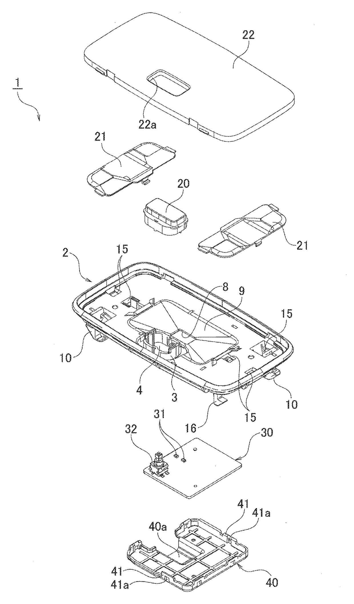
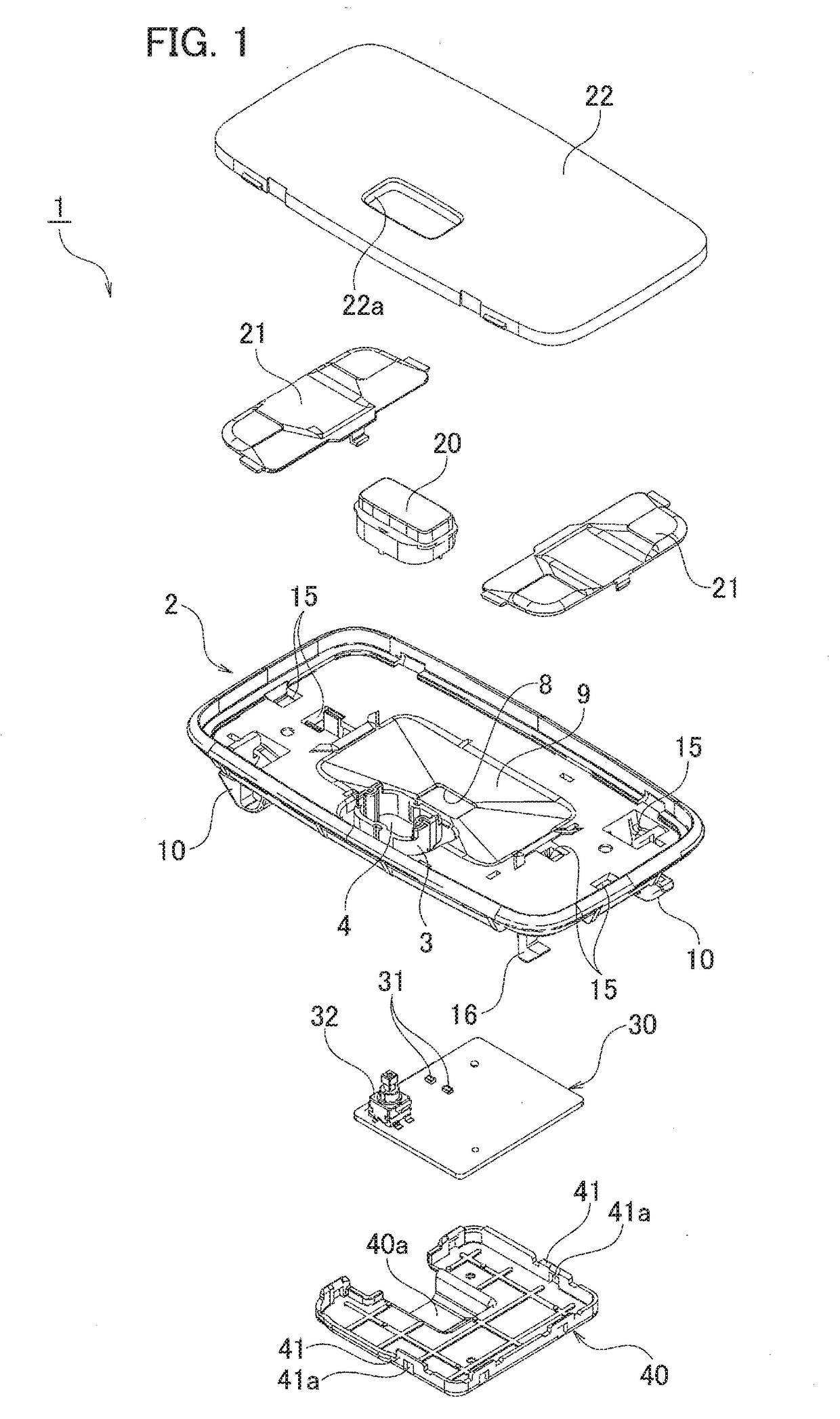
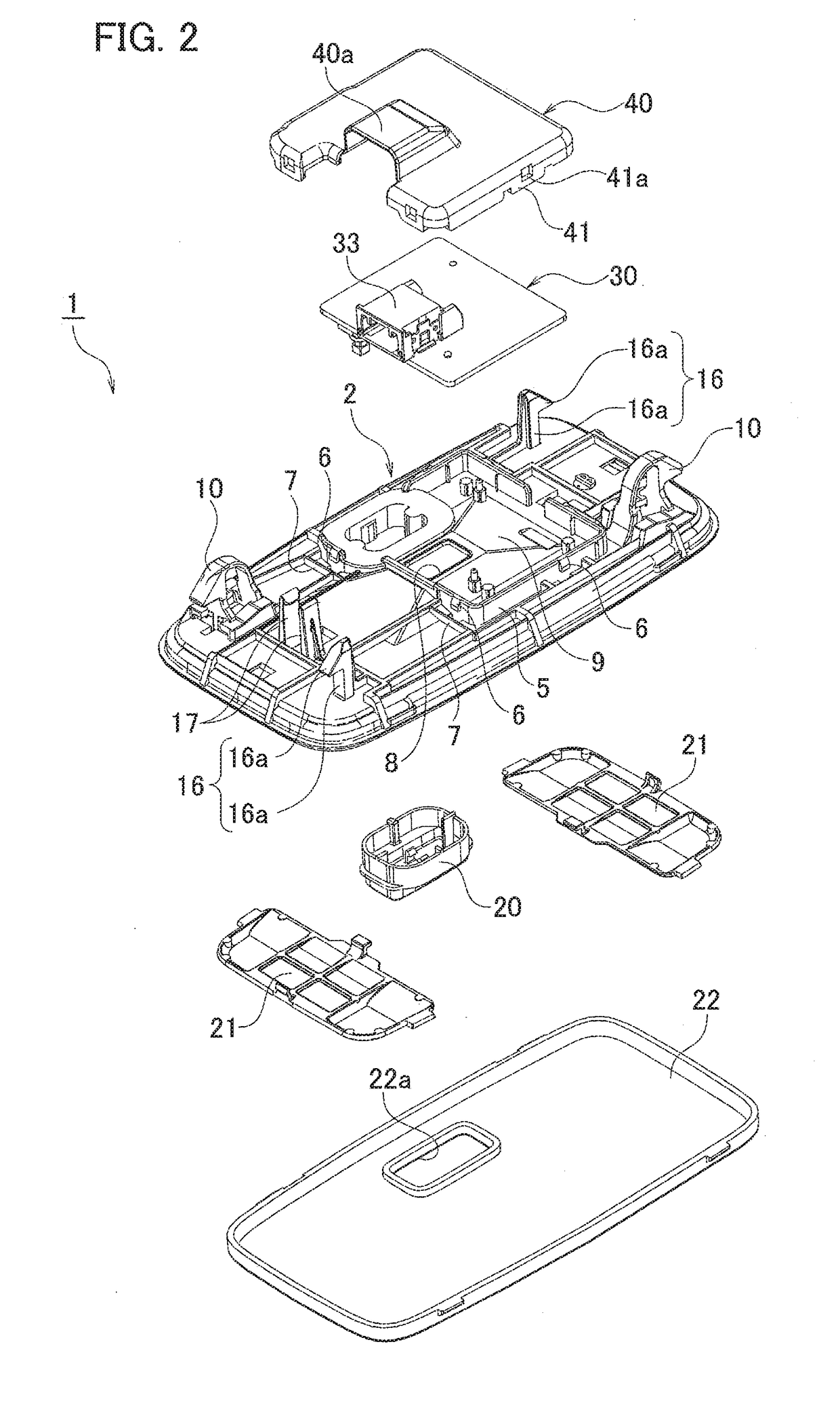
[0024]As illustrated in FIGS. 1 to 4B, an indoor illumination lamp 1 according to an embodiment is installed on a ceiling in an interior of a vehicle. The indoor illumination lamp 1 includes a housing 2 capable of being attached to a ceiling in the interior of the vehicle, a switch knob 20 to be mounted to the housing 2 from below; two inner covers 21 to be attached below the housing 2, a lens cover 22 to be attached below the housing 2, a substrate 30 provided at an upper position of the housing 2, and a substrate cover 40 to be attached above the housing 2. Directions of below and above mean directions in a state where the indoor illumination lamp 1 is installed on the ceiling.

[0025]The housing 2 is formed of a light nontransparent member. As illustrated in detail in FIGS. 1, 2, 5A and 5B, a knob attachment wail 3 is provided on a lower surface side of...


PUM


Abstract

An indoor illumination lamp includes a housing capable of being attached to a ceiling in an interior of a vehicle and provided with a light source opening, a lens cover provided below the housing so as to cover the light source opening, a substrate provided on the upper side of the housing and provided with a light source at a position facing the light source opening, a substrate cover provided on the upper side of the substrate and the housing so as to cover the substrate, and an inclined plane part provided at the housing and inclined upward toward a position where the light source opening is formed.

Description

CROSS REFERENCE TO RELATED APPLICATION[0001]The present application is based on, and claims priority from Japanese Patent Application No. 2017-097231, filed May 16, 2017, the disclosure of which is hereby incorporated by reference herein in its entirety.TECHNICAL FIELD[0002]The present application relates to an indoor illumination lamp to be installed on a ceiling in an interior of a vehicle or the like.BACKGROUND ART[0003]An indoor illumination lamp disclosed in JP 5162420 B has been proposed as a conventional indoor illumination lamp to be installed on a ceiling in an interior of a vehicle or the like. As illustrated in FIGS. 10 to 12, the conventional indoor illumination lamp 100 includes a housing 101 including a ceiling attachment unit 102 which can be attached to a ceiling in the interior of a vehicle, a lens cover 110 attached below the housing 101, and a function unit 120 mounted on the upper side of the housing 101.[0004]The housing 101 is provided with a light source openi...

Claims


Application Information

Patent Timeline
IPC IPC(8): B60Q3/51B60Q3/60B60Q3/82B60Q3/74
CPCB60Q3/51B60Q3/60B60Q3/82B60Q3/74F21S8/00F21V5/04F21V15/01F21V23/04F21W2106/00
Inventor OHTSUKA, HARUHITO
Owner YAZAKI CORP
Why Eureka
Try Eureka