Document feeder and image forming apparatus

Active Publication Date: 2020-04-23
SHARP KK
View PDF5 Cites 0 Cited by
  • Summary
  • Abstract
  • Description
  • Claims
  • Application Information

AI Technical Summary

Benefits of technology

[0015]According to at least an embodiment of the present invention, a substrate is obliquely disposed t

Problems solved by technology

Consequently, the output tray is dark, and sometimes the user fails to notice documents output on

Method used


Image

  • Document feeder and image forming apparatus
  • Document feeder and image forming apparatus
  • Document feeder and image forming apparatus

Examples


first embodiment

[0026]An image forming apparatus according to a first embodiments of the present invention will now be described with reference to the accompanying drawings.

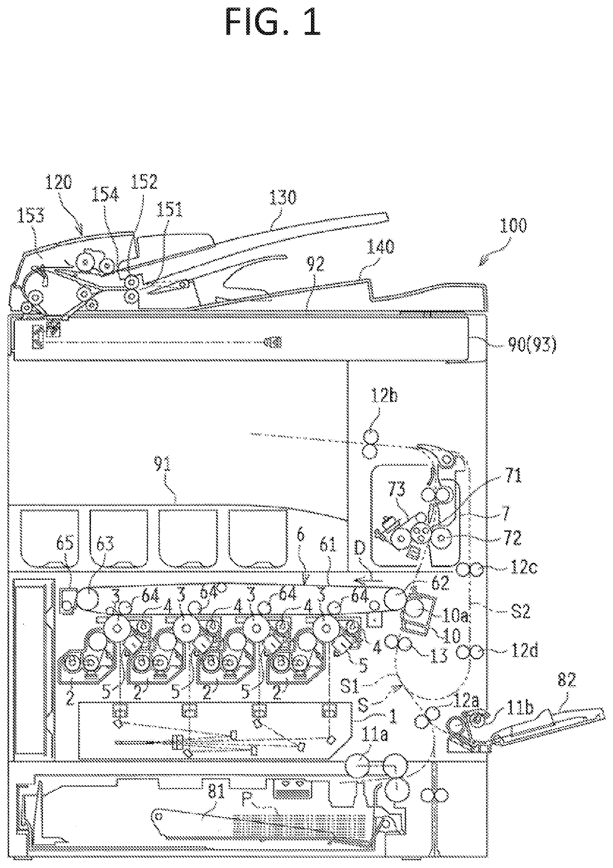
[0027]FIG. 1 is a schematic side view of an image forming apparatus 100 according to the first embodiment of the present invention.

[0028]The image forming apparatus 100 is a multifunction peripheral functioning as a scanner, a copier, a printer, a facsimile machine, etc. The image forming apparatus 100 sends an image of a document read by an image reader 90 to an external device (i.e., functions as a scanner), and forms a multicolor or monochrome image of the read document or an image received from an external device on a sheet (i.e., functions as a copier, a printer, and a facsimile machine).

[0029]The image reader 90 supports a document feeder 120 or automatic document feeder (ADF) so as to allow the document feeder 120 to be freely opened and closed. The image reader 90 includes an image reading unit 93 including a light sourc...

second embodiment

[0072]An image forming apparatus (document feeder) according to a second embodiments of the present invention will now be described with reference to the accompanying drawings. The structure of the image forming apparatus according to the second embodiment is substantially the same as that of the first embodiment. Thus, the same reference numerals are used and redundant descriptions and drawings are omitted.

[0073]FIG. 10 is a schematic cross-sectional view of the structure of a substrate and its vicinity according to the second embodiment of the present invention.

[0074]The structure of the opening portion 133 and its vicinity in the second embodiment differs from that in the first embodiment. In specific, the opening portion 133 has a taper 133b having a gradually varying thickness. The taper 133b is obliquely disposed such that the opening is small in the inner face and large in outer face. In the case where the opening portion 133 has the taper 133b, the slit member 133a may be om...

third embodiment

[0075]An image forming apparatus (document feeder) according to a third embodiments of the present invention will now be described with reference to the accompanying drawings. The structure of the image forming apparatus according to the third embodiment is substantially the same as that of the first and second embodiments. Thus, the same reference numerals are used and redundant description and drawings are omitted.

[0076]In the first embodiment, the optical axis of the light source 161 tilts with respect to the output direction H. In the third embodiment, the optical axis of the light source 161 also tilts relative to the width direction Y. In specific, the optical axis of the light source 161 tilts toward the front side in the width direction Y. Such a configuration can increase the area of the irradiation range SR toward the front side, thereby illuminating the area close to the user. Thus, the light is made noticeable to the user.


PUM


Abstract

A document feeder includes an input tray (part of a document placing portion) on which a document is placed, an output tray on which the document output from a document output port in an output direction is stacked, and a substrate including a light source that emits light to the output tray. The output tray is disposed below the input tray. The substrate is fixed to the document placing portion at an oblique angle relative to a horizontal reference of the document feeder such that the optical axis of the light source extends toward the document output port.

Description

BACKGROUND OF THE INVENTIONField of the Invention[0001]The present invention relates to a document feeder that transports a document and an image forming apparatus.Description of the Background Art[0002]A known document feeder disposed in an image forming apparatus takes in a document placed on an input tray, and outputs the document on an output tray after the document is read. In the document feeder, the input tray is disposed above the output tray. Consequently, the output tray is dark, and sometimes the user fails to notice documents output on the dark output tray. A light source that emits light to the output tray has been proposed to prevent such a document to be left unnoticed (for example, Japanese Unexamined Patent Publication No. 2013-197725).[0003]The image reader according to Japanese Unexamined Patent Publication No. 2013-197725 includes a document placing portion that holds documents; a document transporter that transports a document placed on the document placing port...

Claims


Application Information

Patent Timeline
IPC IPC(8): H04N1/00
CPCH04N1/00636H04N2201/0094H04N1/0049H04N1/00591H04N1/00599H04N1/00278
Inventor KURODA, KENJIFUKUTOME, SHOHICHIOGASAWARA, HIRONORIYAMANAKA, HISASHIFUKUNISHI, TOSHIKI
Owner SHARP KK
Why Eureka
Try Eureka