Method and device for greatly increasing irradiation range of street lamp

a street lamp and irradiation range technology, applied in semiconductor devices, light sources, lighting and heating devices, etc., can solve the problems of pilots erroneously identifying the navigation light as navigation light, adversely affecting the flying of airplanes at high altitude, and light pollution, so as to increase the irradiation range of street lamps or high-pole lamps

Active Publication Date: 2017-09-07
HONGLI LIGHTING GRP
View PDF0 Cites 4 Cited by
  • Summary
  • Abstract
  • Description
  • Claims
  • Application Information

AI Technical Summary

Benefits of technology

[0007]One aspect of the present disclosure includes a method for greatly increasing an irradiation range of a street lamp or a high-pole lamp. The method includes: firstly, a COB module LED area light source is adopted as a light source; secondly, the LED area light source is put into an incident concave surface to be covered by the same, so that the LED point light source is primarily refracted by the incident concave surface; thirdly, a light-distribution free curved surface is further arranged to cover the incident concave surface, so that the light ray primarily refracted by the incident concave surface is subsequently refracted by the light-distribution free curved surface to deflect by a large angle.
[0018]The light distribution angle θ1 falls into a range from the included angle of the optical axis and + / −ψ. The positive and negative signs of the light angles are defined as the same herein: the light ray deflecting toward the left of the optical axis OZ is negative, while the light ray deflecting toward the right of the optical axis OZ is positive. The street lamp lens or the high-pole lamp lens capable of greatly increasing the irradiation range of the street lamp of claim 1, wherein the light-distribution free curved surface is approximately 102.2092285 mm in width and approximately 50.8887939 mm in height, and the errors of all the dimensions are approximately + / −1 mm.

Problems solved by technology

Currently, the required illumination distance of a street lamp is at least 75 m, while a light-distribution deflection angle of an optical lens or a reflecting cup is insufficient, therefore, the existing LED high-pole lamps for plaza illumination are often mounted at a large elevation angle, and light emitted from the LED high-pole lamps can be projected onto the ground opposite to a lamp pole.
In addition, a large amount of light emitted from the LED high-pole lamps is directly projected to the sky, causing light pollution.
Thus, strong glare is often generated by the high-pole lamps and directly emitted to the sky, which adversely affects airplanes flying at high altitudes.
For example, pilots may erroneously identify it as navigation lights.
Further, the strong light emitted to the sky illuminates the clouds, forming noisy background light and blocking the starlight.
Due to the insufficient deflection angles, the light emitted by the optical lenses cannot reach as far as 6-7 lanes, thus fails to meet the road illumination requirement of 6-7 lanes.

Method used


Image

  • Method and device for greatly increasing irradiation range of street lamp
  • Method and device for greatly increasing irradiation range of street lamp
  • Method and device for greatly increasing irradiation range of street lamp

Examples


Embodiment Construction

[0033]Reference will now be made in detail to exemplary embodiments of the invention, which are illustrated in the accompanying drawings. Hereinafter, embodiments consistent with the disclosure will be described with reference to drawings. It is apparent that the described embodiments are some but not all of the embodiments of the present invention. Based on the disclosed embodiments, persons of ordinary skill in the art may derive other embodiments consistent with the present disclosure, all of which are within the scope of the present invention.

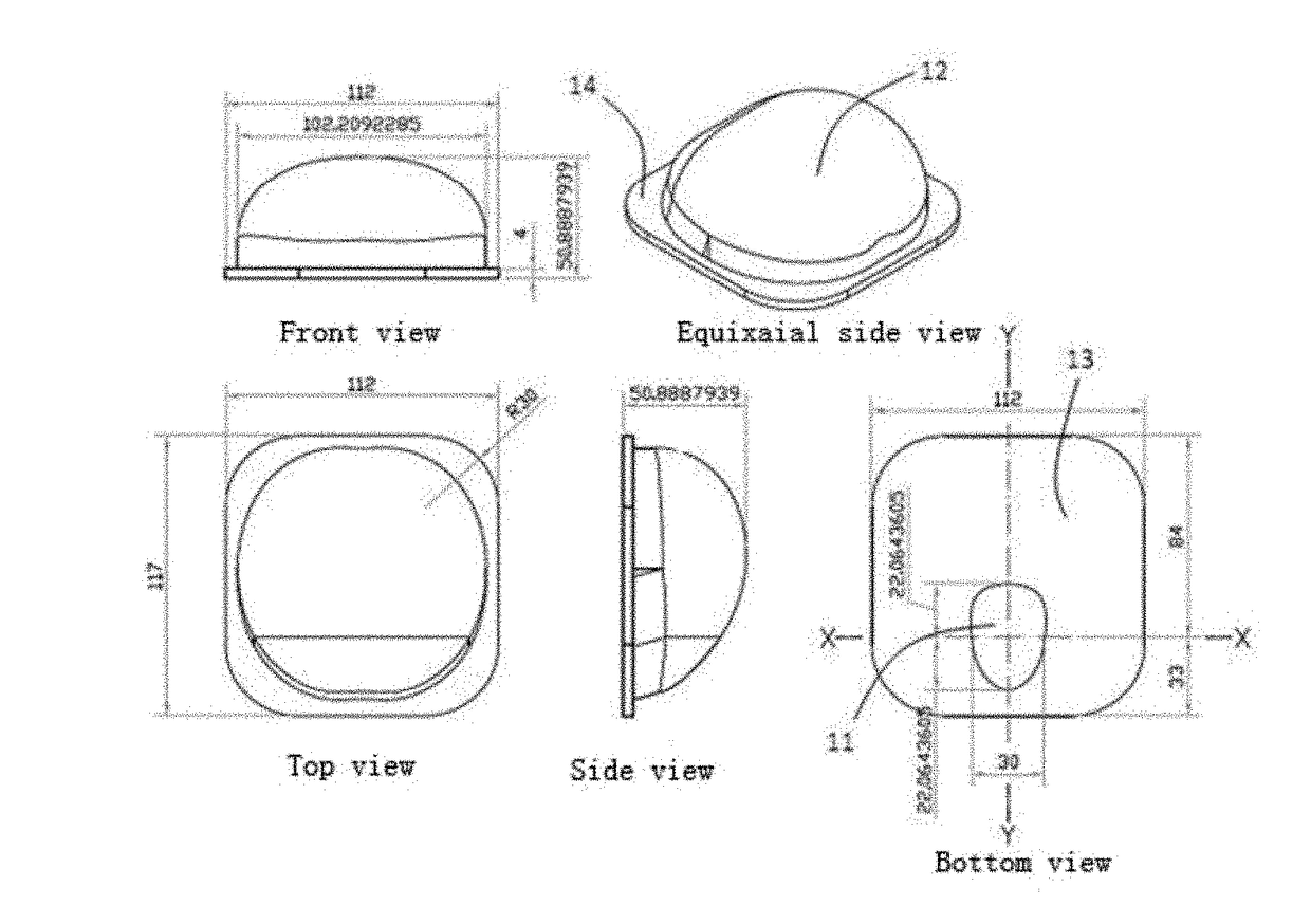
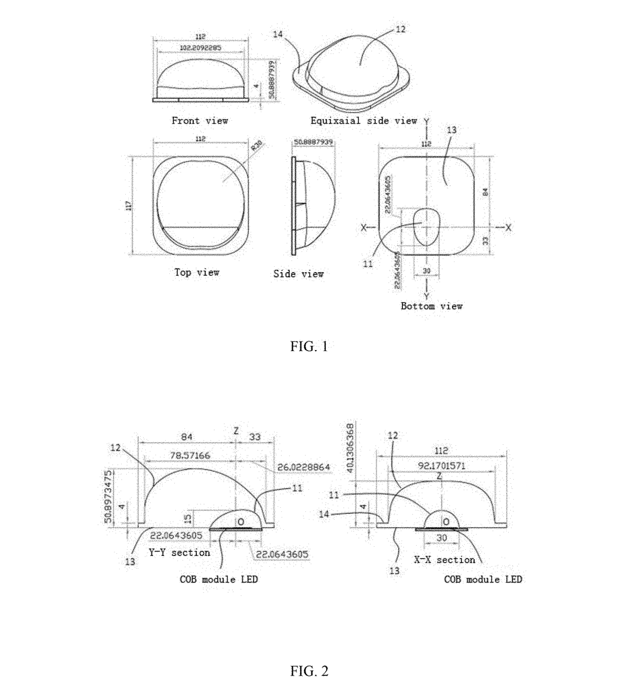
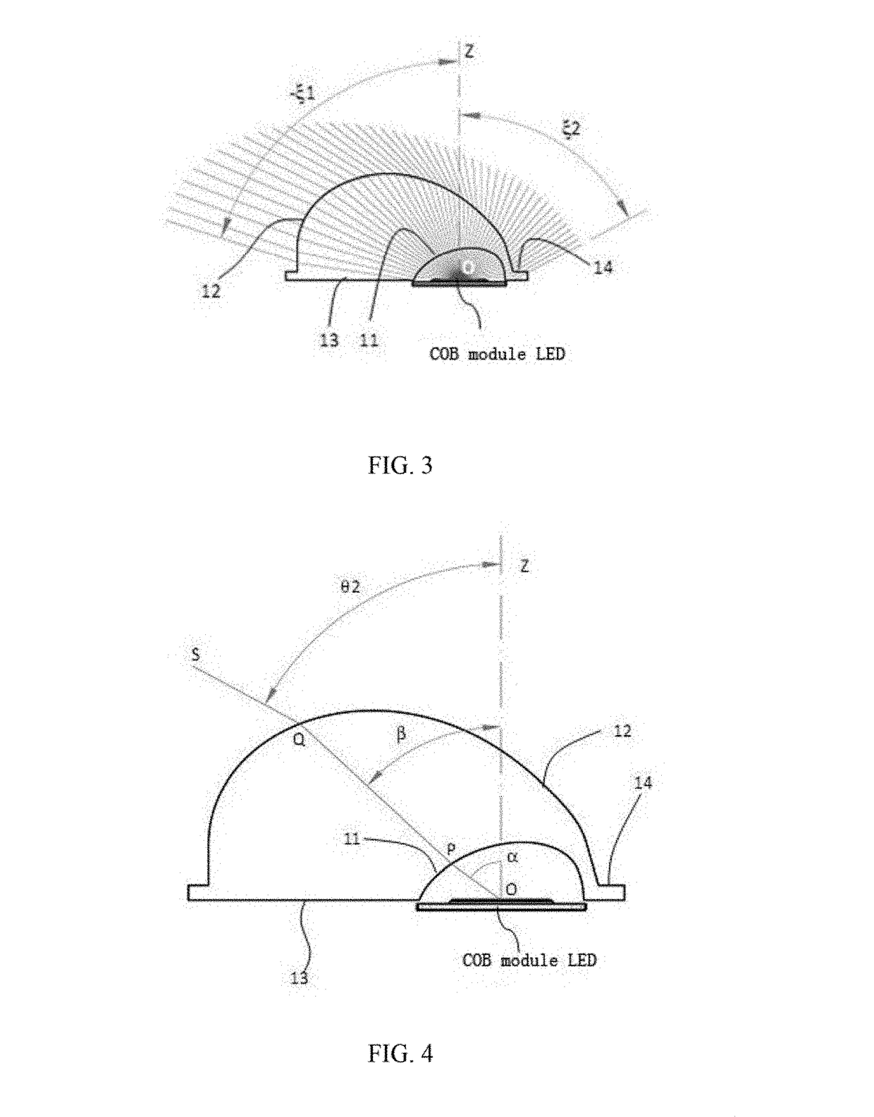
[0034]The present disclosure provides a method for greatly increasing the irradiation range of a lamp, which is directed to solve the problem that the existing LED illuminating street lamps are not able to satisfy the illumination of street lamps on one single side to more than 6 lanes or plaza illumination due to unreasonable design of the secondary optical lenses.

[0035]The present invention is further described below by combining the acco...


PUM


Abstract

The invention provides a method and a device for greatly increasing an irradiation range of a lamp. The method is characterized as follows: firstly, a COB module LED point light source is adopted as a light source; secondly, the LED point light source is put into an incident concave surface (11) to be covered by the same, so that the LED point light source is primarily refracted by the incident concave surface (11); thirdly, a light-distribution free curved surface (12) is further arranged to cover the incident concave surface (11), so that the light ray primarily refracted by the incident concave surface (11) is subsequently refracted by the light-distribution free curved surface (12) to deflect by a large angle; after two refractions, the included angle between a position, perpendicular to an extension direction of a road, of the peak intensity and an optical axis ranges from 60 to 75 degrees and a light distribution angle in a direction in accordance with the extension direction of the road ranges from 120 to 150 degrees, whereby the illumination of one single COB module LED point light source to at least 6 lanes and illumination at an interval of at least 35 m or long-distance illumination of a high-pole lamp are realized. The method and the device of the present invention are capable of realizing the illumination of one single lamp to at least 6 lanes.

Description

CROSS-REFERENCES TO RELATED APPLICATIONS[0001]This application is a national stage patent application of PCT application No. PCT / CN2014 / 092328, filed on Nov. 27, 2014. This application claims priority to Chinese Patent Application No. 201310690220.7, filed on Dec. 16, 2013, the entire content of which is incorporated herein by reference.FIELD OF THE INVENTION[0002]The present disclosure generally relates to a lighting technology, in particular relates to a method and a device capable of realizing road illumination to at least 6 lanes with an interval of less than 45 m through one single light source or high-pole lamp illumination by virtue of a light distribution technology, and specifically relates to a method and a device for greatly increasing the irradiation range of a lamp.BACKGROUND[0003]Currently, the required illumination distance of a street lamp is at least 75 m, while a light-distribution deflection angle of an optical lens or a reflecting cup is insufficient, therefore, ...

Claims


Application Information

Patent Timeline
Patent Type & Authority Applications(United States)
IPC IPC(8): F21V5/04F21S8/08
CPCF21V5/04F21Y2115/10F21W2131/103F21S8/085F21S8/086
Inventor LV, GUOFENGLV, WENQING
Owner HONGLI LIGHTING GRP
Why Eureka
Try Eureka