Paver stone, brick and block extraction tool

a technology of stone, brick and block extraction and tool, which is applied in the field of tools and lifting systems, can solve the problems of prone failure of the tabs disclosed in weber, and none of the foregoing prior art discloses a reliable, scalable device, and achieves the effect of greater mechanical lifting for

Active Publication Date: 2018-11-29
MARTELLE DAVID JAY
View PDF5 Cites 3 Cited by
  • Summary
  • Abstract
  • Description
  • Claims
  • Application Information

AI Technical Summary

Benefits of technology

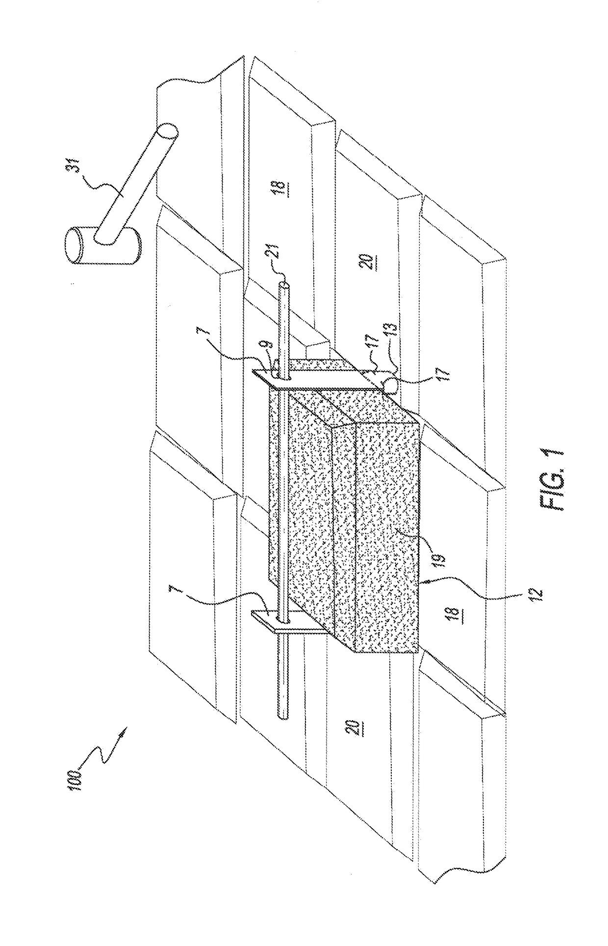
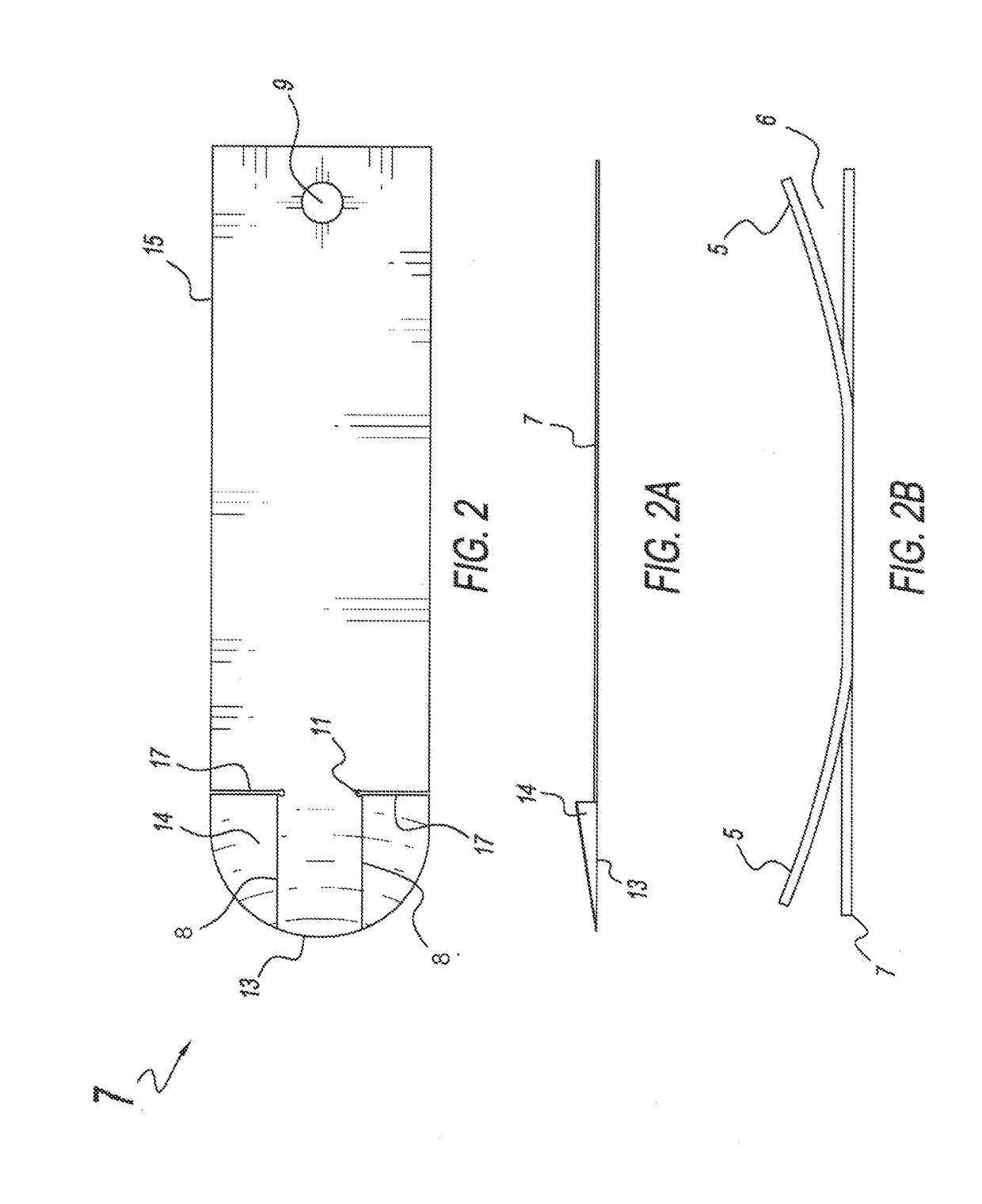
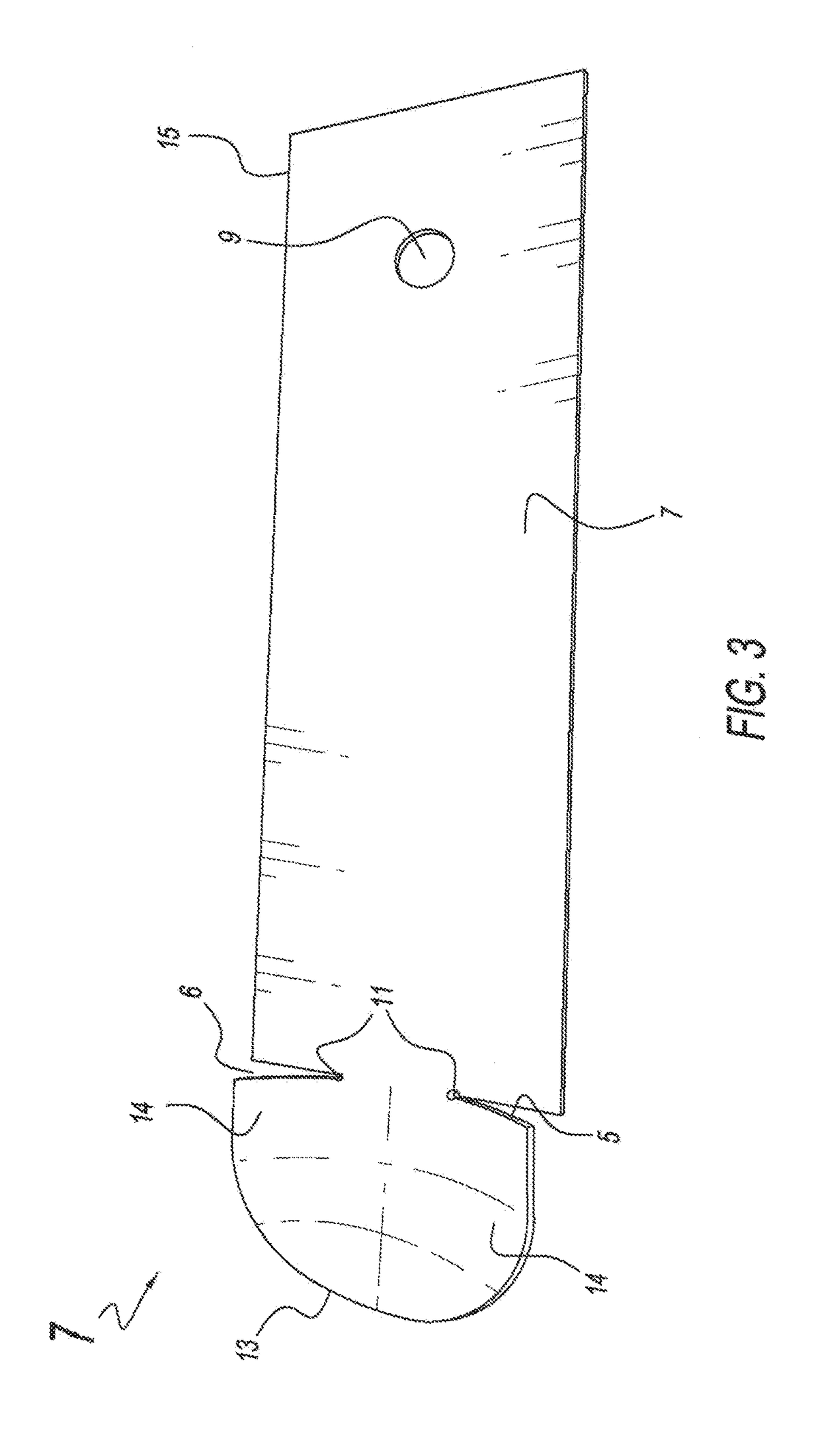
[0008]The present invention discloses an improved tool and system for the extraction of a paver stone, tile, brick or block that is not permanently fixed in place with cement, thin set or similar material. The device uses one or more lifting plates and a lifting aid each of which are more particularly described below. The lifting plates are inserted or wedged into existing gaps between the paver to be extracted and one or more adjacent pavers. The lifting plates may be joined using the lifting aid, such as a rod or handle as more particularly described below, though the lifting plates are useful for extracting a paver without the necessity of the lifting aid. By way of example and not limitation, a lifting plate may be wedged as described above, with a force sufficient to compress the blade end of the lifting plate to a depth that permits the blade tabs to de-compress and re-form such that the tab edges engage with the bottom side of the paver to be extracted. Once the tab edges engage with the bottom side of the paver, the paver may be extracted; however, a user may also join one or more lifting plates together with a lifting aid. The lifting aid together with the lifting plates may assist the user in overcoming frictional resistance and applying a greater mechanical lifting force, and also providing user comfort.

Problems solved by technology

In addition, the tabs disclosed in Weber are prone to failure due to repeated bending and flexing combined with stress that is concentrated on an area that is proportionally smaller than in the present invention.
None of the foregoing prior art discloses a reliable, scalable device that solves the problem of extracting a paver stone, tile, brick, block or the like, irrespective of dimension and weight.

Method used


Image

  • Paver stone, brick and block extraction tool
  • Paver stone, brick and block extraction tool
  • Paver stone, brick and block extraction tool

Examples


Embodiment Construction

[0029]It is to be understood that the figures and descriptions of the present invention have been simplified to illustrate elements that are relevant for a clear understanding of the invention. Those of ordinary skill in the art may recognize that other elements and / or steps may be desirable in implementing the present invention. However, because such elements and steps are well known in the art, and because they do not facilitate a better understanding of the present invention, a discussion of such elements and steps is not provided herein. Throughout the following detailed description the same reference numerals refer to the same elements in all figures.

[0030]The following detailed description includes the best mode of carrying out the invention and is made for the purpose of illustrating the general principles of the invention and should not be taken in a limiting sense. The scope of the invention is determined by reference to the claims. Each part or function is assigned, even i...


PUM


Abstract

An apparatus for extracting a paver stone, and the like from a preset position, including a pair of lifting plates having a body containing one or more lifting aid insertion openings at one end, and at an opposing end, a blade portion having substantially concave tabs with tab edges formed along a pair of slots terminating in one or more of stress relief openings between the body and the blade, wedging a first blade between the paver and a first adjacent paver and wedging a second blade at an opposing end of a paver and a second adjacent paver, substantially compressing the tabs storing spring energy in the blades, pushing the tab edges below the bottom plane of the paver, releasing the stored spring energy thereby substantially decompressing and re-forming the tabs such that the tab edges contact and engage the underside of the paver to be extracted.

Description

FIELD OF THE INVENTION[0001]The present invention relates to a tool and lifting system for extracting a paver stone and the like from its preset position.BACKGROUND OF THE INVENTION[0002]Tools for lifting or extracting preset paver stones are broadly known in the art as exemplified in the following described patents.[0003]U.S. Pat. No. 705,227 issued to McDowell on Jul. 22, 1902 is directed to a lifting implement constructed to enable the gripping and carrying of bricks and includes two jaw members connected by a ratcheting bar used to adjust for the number of bricks to be lifted or carried and exert a compression force between the jaw members.[0004]U.S. Pat No. 1,586,475 issued May 25, 1926 to Schondelmayer et al. discloses a mechanism that allow the altering of a space between a pair of jaws to accommodate the varying dimensions of a brick, and wherein a single uppermost pivoted handle provides compression force between jaw elements.[0005]U.S. Pat. No. 5,509,706 issued Apr. 23, 19...

Claims


Application Information

Patent Timeline
Patent Type & Authority Applications(United States)
IPC IPC(8): E01C23/12E04G21/16B65G7/12
CPCE01C23/121E04G21/162B65G7/12E01C19/52
Inventor MARTELLE, DAVID JAY
Owner MARTELLE DAVID JAY
Why Eureka
Try Eureka