
Gas combustion-type driving tool

a driving tool and gas combustion technology, applied in the direction of manufacturing tools, nailing tools, stapling tools, etc., can solve the problems of troublesome exchanging procedure of spring members, complicated and troublesome exchanging procedures of spring members, and the height of the entire gas combustion-type driving tool becomes high, so as to achieve good maintenance properties and easy use of tools

Active Publication Date: 2010-09-30
MAX CO LTD
View PDF6 Cites 0 Cited by
  • Summary
  • Abstract
  • Description
  • Claims
  • Application Information

AI Technical Summary

Benefits of technology

[0011]One or more embodiments of the invention provides a gas combustion-type driving tool in which the entire height and the outer diameter of the gas combustion-type driving tool are suppressed to be small, whereby the miniaturization and light-weight of the tool can be realized, the workability at a narrow place etc. can be improved, the tool can be used easily, and the maintenance property of the tool is good since the elastic member can be exchanged easily.
[0014]According to the first aspect of the invention, it is not necessary to provide the dedicated space for disposing elastic members unlike the related art. Thus, the entire height of the tool can be suppressed to be low as compared with the case where the elastic member is provided at a dedicated space beneath the driving cylinder at the lower portion of the driving cylinder. Similarly, since the elastic member is not disposed at the front portion of a nose portion or around the driving cylinder, the outer diameter of the tool can also be suppressed so as not to be large, which contributes to the miniaturization and the light-weight. Further, since the driving operation can be performed in a state that the tip end of the nose portion is inserted into a narrow space, the operability and the handling property can also be improved.
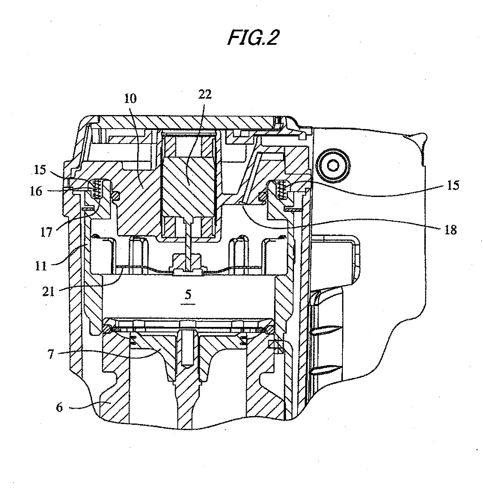
[0016]According to the second aspect of the invention, since the elastic members, each of which one end and the other end being engaged and locked with the movable sleeve and the cylinder head portion respectively, are disposed so as to have the same interval therebetween around the axis of the driving cylinder, the balance of the elastic members is good and so the movable sleeve can be operated smoothly and surely.

Problems solved by technology

However, in a system where an elastic member such as a spring member is provided beneath a cylinder like the gas combustion-type driving tool shown in FIG. 9 of the Patent Document 2, it is required to provide a dedicated space for disposing the elastic member and so there arise a problem that the entire height of the gas combustion-type driving tool becomes high.
Thus, there arises a problem that a size around the nose portion becomes larger and so it is difficult to drive a nail in a narrow space etc.
Further, according to the aforesaid arrangements of the spring member, there arises a problem that the exchanging procedure of the spring member is complicated and troublesome.

Method used


Image

  • Gas combustion-type driving tool
  • Gas combustion-type driving tool
  • Gas combustion-type driving tool

Examples


Embodiment Construction

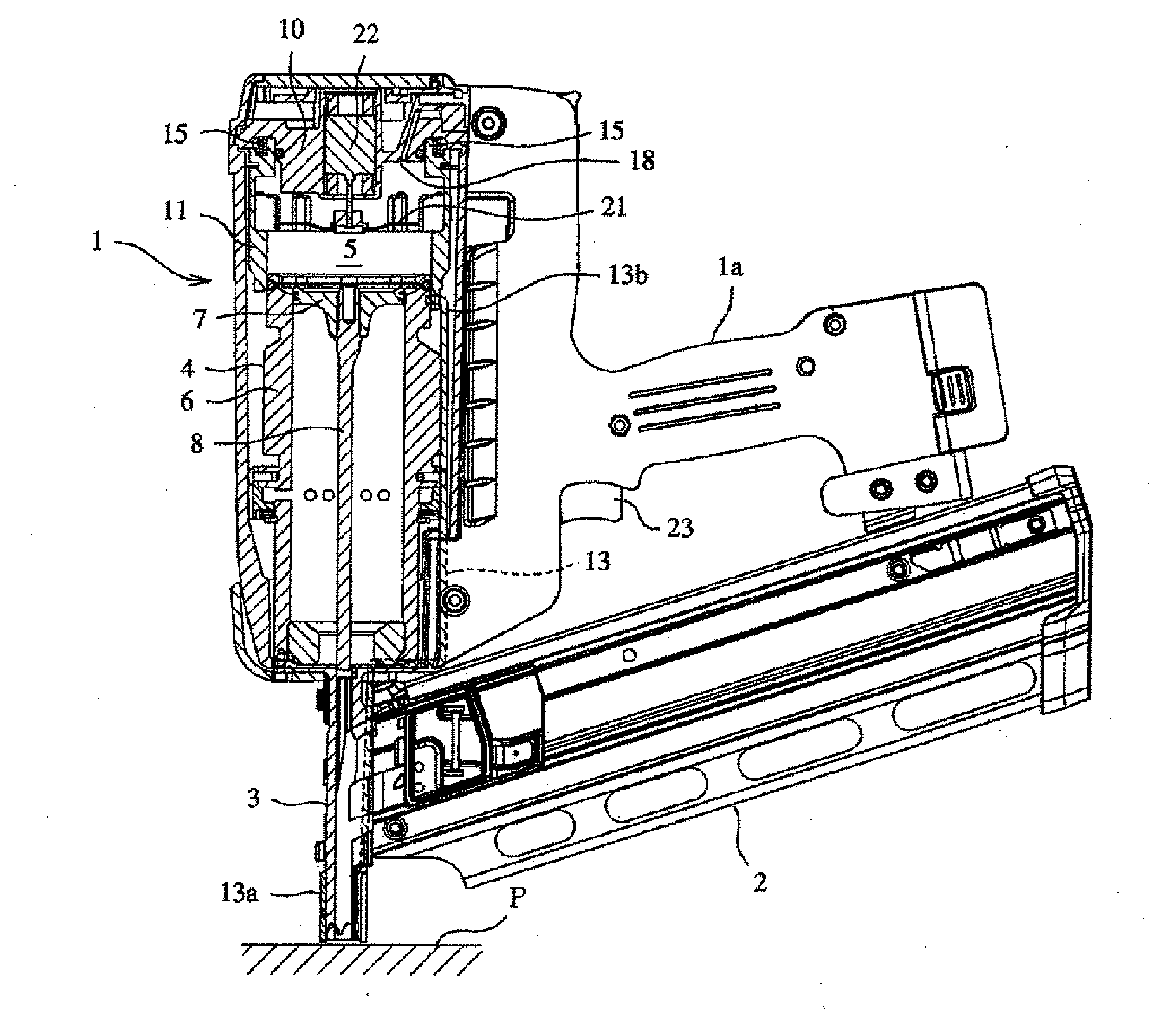
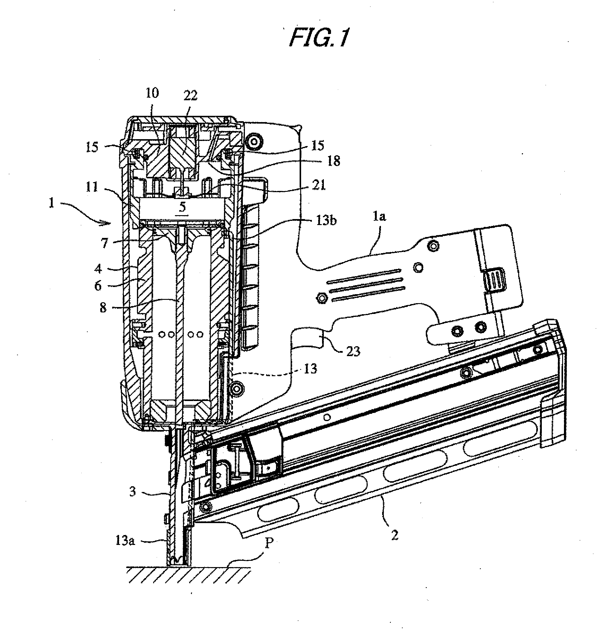
[0030]An embodiment of the invention will be explained with reference to FIGS. 1 to 3 in which the gas combustion-type driving tool according to the invention is applied to a nailer. FIG. 1 is an entire diagram showing a driving state of the gas combustion-type driving tool, FIG. 2 is an enlarged diagram showing the main portion of the tool and FIG. 3 is an enlarged diagram showing the main portion thereof in a non-operation state.

[0031]In FIGS. 1 and 2, a reference numeral 1 depicts the body of the gas combustion-type driving tool. A grip 1a and a magazine 2 are coupled to the body 1 and a driving piston / cylinder mechanism 4 is provided within the body. A nose portion 3 for driving out a nail is provided at the lower portion of the body 1.

[0032]The driving piston / cylinder mechanism 4 houses a driving piston 7 within a driving cylinder 6 so as to be freely slidable and a driver 8 is integrally coupled at the lower portion of the driving piston 7.

[0033]Next, a combustion chamber 5 is...


PUM

PropertyMeasurementUnit
pressureaaaaaaaaaa
diameteraaaaaaaaaa
heightaaaaaaaaaa

Abstract

A driving piston 7 is provided so as to be slidable in an up-down direction within a driving cylinder 6 disposed within a body 1. A movable sleeve is fitted on the outer peripheral side of the driving cylinder 6 on the cylinder so as to be movable in the up-down direction. When the movable sleeve 11 is moved upward to abut against a cylinder head 10 provided in the upper direction, a sealed combustion chamber 5 is formed. When combustible mixed gas is explosively burnt within the combustion chamber 5, high-pressure combustion gas acts on the driving piston 7 to thereby impulsively drive the piston, whereby a fastener is driven out by a driver 8 coupled on the lower surface side of the driving piston 7. Elastic members 15 are disposed between the movable sleeve 11 and the cylinder head 10. The elastic members 15 bias the movable sleeve 11 downward.

Description

TECHNICAL FIELD[0001]The present invention relates to a gas combustion-type driving tool for driving a faster such as a nail.BACKGROUND ART[0002]In general, in a gas combustion-type driving tool, a driving piston is provided so as to be slidable in an up-down direction within a driving cylinder disposed within a body. A tubular movable sleeve is fitted on the outer peripheral side of the driving cylinder on the cylinder so as to be movable in the up-down direction. The movable sleeve is biased downward by a spring so as to be always located at the lower position. Upon a striking operation, the movable sleeve is moved upward against the spring and abuts to a cylinder head provided at above the driving cylinder to thereby form an air tight combustion chamber. Then, when combustion gas within the combustion chamber is ignited and explosively burnt, a driver is driven together with the driving piston to drive out a fastener.[0003]Conventionally, a spring member for biasing the movable s...

Claims


Application Information

Patent Timeline
Patent Type & Authority Applications(United States)
IPC IPC(8): B25C1/14
CPCB25C1/08B25C1/10B25C1/14B25C1/18
Inventor OSUGA, SATOSHI
Owner MAX CO LTD
Learn More