High q-factor magnetic resonance imaging radio frequency coil device and methods

a radio frequency coil and q-factor technology, applied in the field of radio frequency coils, can solve the problems of affecting the performance of the surface coil, causing unwanted heating, and required high rf frequencies, and achieve the effect of reducing the flow of countercurren

Inactive Publication Date: 2018-11-29
THE MEDICAL COLLEGE OF WISCONSIN INC
View PDF0 Cites 4 Cited by
  • Summary
  • Abstract
  • Description
  • Claims
  • Application Information

AI Technical Summary

Benefits of technology

[0013]It is still another aspect of the present invention to provide a high Q-value coil that includes a conductive assembly having at least two overlapping conductive elements that define an overlap area therebetween, and a dielectric material coupled to the conductive assembly. The dielectric material also provides a separation distance between the at least two conductive elements in the overlap area. A thickness of a conductor in the conductive assembly is selected to minimize countercurrents flowing in the conductive assembly.

Problems solved by technology

However, with this increased magnetic field strength, high RF frequencies are required.
This increase in resistance can negatively impact the performance of a surface coil, as well as induce unwanted heating due to the increased ohmic resistance.
As skin depths can be extremely shallow at the RF frequencies required for high field strength MRI magnets, the Q-value can be significantly impacted.
Another disadvantage of present surface coil MRI systems is their limited field of view.
However, these array based surface coil MRI systems have their disadvantages, as placing surface coils in proximity to each other can result in an adverse “proximity effect.” Proximity effect occurs when adjacent conductors are carrying a current, and the magnetic field produced by one or more of the adjacent conductors affects the current distribution in another adjacent conductor.

Method used


Image

  • High q-factor magnetic resonance imaging radio frequency coil device and methods
  • High q-factor magnetic resonance imaging radio frequency coil device and methods
  • High q-factor magnetic resonance imaging radio frequency coil device and methods

Examples


example # 1

Example #1: Folded Gap Loop with 10 Sets of Overlapping Conductors

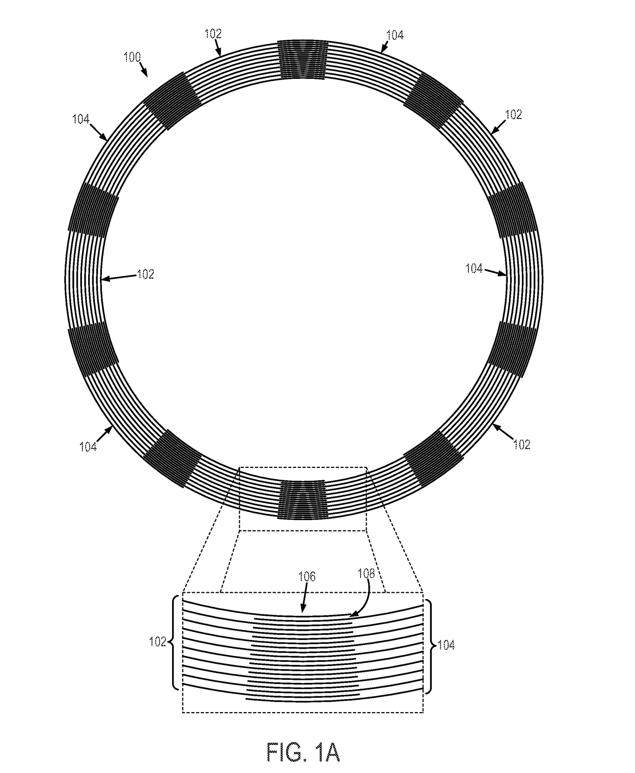
[0106]An example of a meta-metallic structure similar to the one illustrated in FIG. 1A can be constructed to include 10 sets of 10 foil layers that form a loop. Each foil set wraps 51 degrees and overlaps with the next set on each end for 15 degrees. The capacitance of the overlapping regions was designed to resonate with the inductance of the loop at a frequency of 400 MHz. The structure was simulated using the finite element computer program Ansys High Frequency Structure Simulator (HFSS) (Canonsburg, Pa.).

[0107]The current in each layer is directed primarily around the loop. The current is maximum in the non-overlapping regions, decreases in the overlapping regions and goes to zero on the ends of the foils. The current magnitude in a foil layer is substantially proportional to the area of overlap with adjacent foils. For illustration purposes, the foil material was chosen to be stainless steel with a conductivity ...

example # 2

Example #2: Folded Gap Loop with 2 Sets of Overlapping Conductors

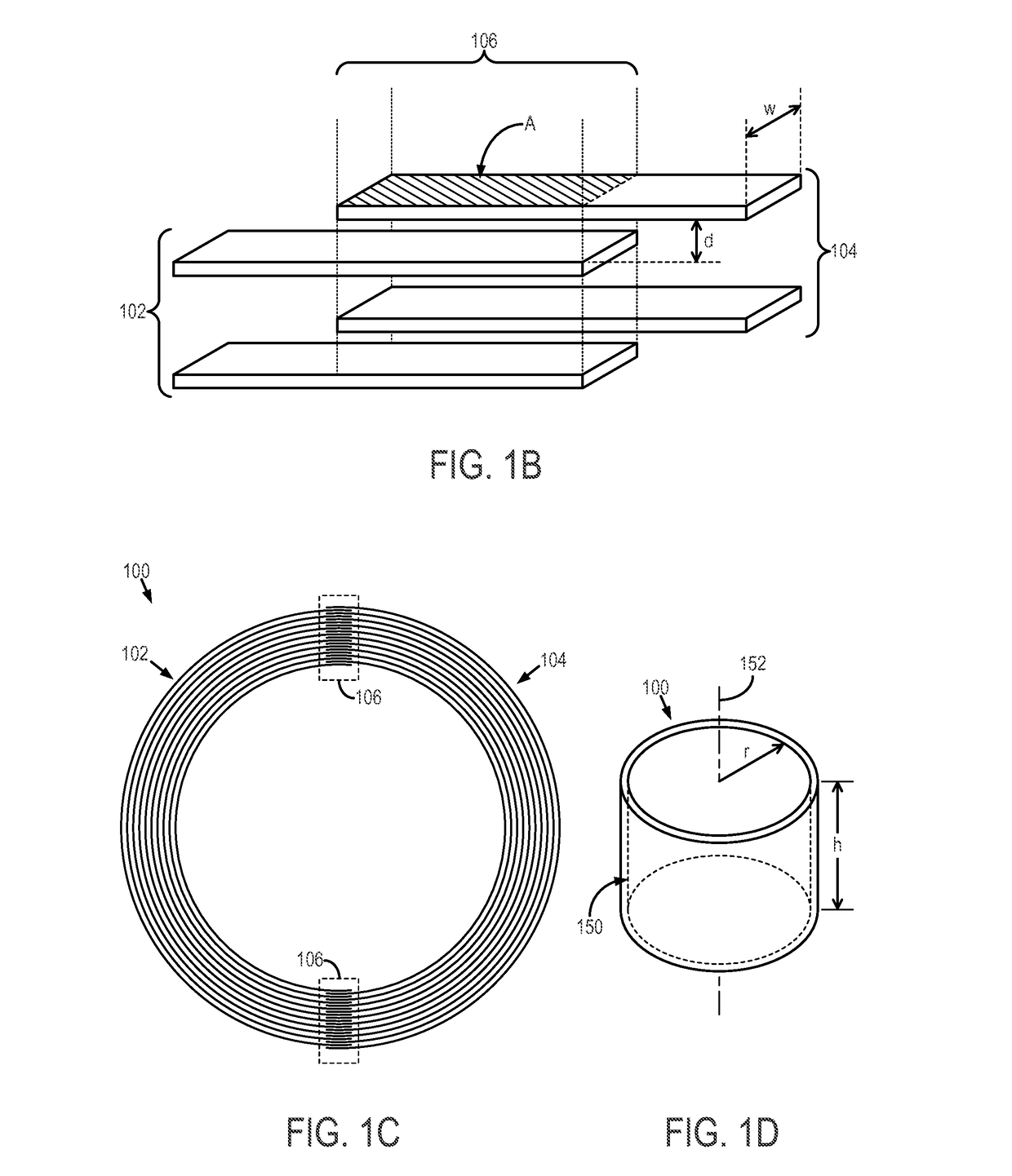
[0117]An example of a meta-metallic structure similar to the one illustrated in FIG. 1C can be constructed to include two sets of 10 foil layers. The structure has an inner radius of 5 mm, an outer radius of 10.8 mm, a spacing between adjacent foil layers of 0.30 mm and an overlap distance of 1.2 mm. By constructing the overlapping foil region with a constant distance instead of angle, the capacitance is constant, which produces more uniform currents across the conductor layers.

[0118]A conducting boundary was placed at a radius of 28 mm. The structure resonates at 393 MHz and, for a foil thickness of 1.6 μm, has a Q-value of 5,514. This can be compared to a Q-value of 1,407 for an LGR of the same inner and outer radius and the same metal. The resulting Q-enhancement ratio is 3.9. The eddy current dissipation lowers the Q-enhancement, as expected. The inductance of this folded-gap loop is approximately 2.5 times higher ...

example # 3

Example #3: Self-Resonant Spiral

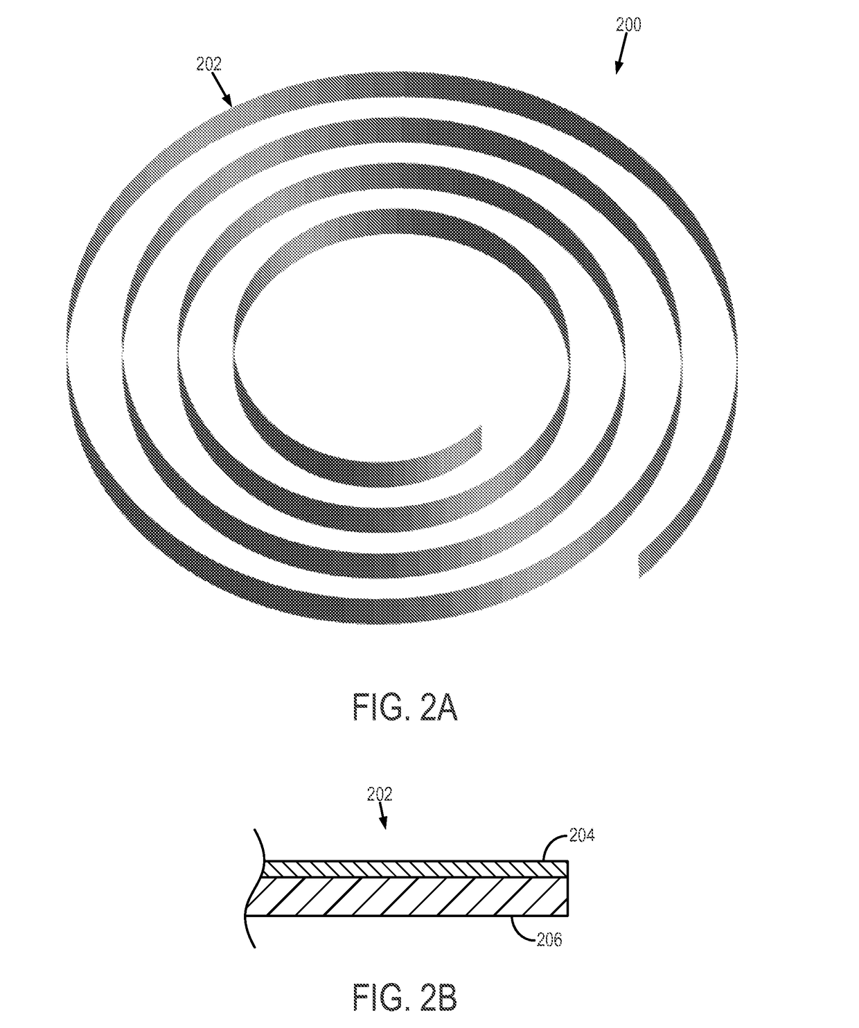
[0119]An example of a meta-metallic structure similar to the one illustrated in FIG. 2A can be constructed to include a single spiral coil with an inner radius of 3 mm, an outer radius of 8 mm, 4 turns, and a foil thickness of 2.2 μm. A conducting boundary was placed at a radius of 20 mm. The resonance frequency of this structure is 407 MHz with a Q-value of 2,169. This compares to a Q-value of 809 for an LGR of the same inner and outer radius.

[0120]Eddy current dissipation is expected to lower the Q-enhancement; however, the example spiral coil has approximately 1.8 times the inductance of the LGR and this factor raises the Q-enhancement ratio. The nearly sinusoidal (nonuniform) current distribution with foil length in the spiral does not have much effect in lowering the Q-enhancement. For the different structure types that have been simulated, it was found that close attention to balancing the currents by equal capacitance does not significantly imp...


PUM


Abstract

High Q-value radio frequency (RF] coils are described. In general, the RF coils include multiple conductor layers that at least partially overlap to define a capacitive region that equalizes current flowing in each conductor. In some instances, the RF coil includes sets of layered conductors, where each set of layered conductors overlaps in an overlap region. In some other instances, the RF coil includes a spiraled conductor coupled to a dielectric material, where the number of turns of the spiral defines the overlap area. Multiple spiraled conductors can be interleaved. An equalization coil can also be provided to equalize currents along an axial dimension of each conductor in such RF coils. The thickness of the conductors is less than three skin depths, and preferably less than one skin depth, to overcome skin-depth limitations.

Description

CROSS-REFERENCE TO RELATED APPLICATIONS[0001]This application claims the benefit of U.S. Provisional Patent Application Ser. No. 62 / 082,492, filed on Nov. 20, 2014, and entitled “HIGH Q-FACTOR RF COIL DEVICE AND METHODS.”STATEMENT REGARDING FEDERALLY SPONSORED RESEARCH[0002]This invention was made with government support under EB001980 and EB00215 awarded by the National Institutes of Health. The government has certain rights in the invention.BACKGROUND OF THE INVENTION[0003]The subject matter disclosed within generally relates to radio frequency (RF) coils, and specifically surface coils for use in Magnetic Resonance Imaging (MRI) systems. MRI systems rely on both magnetic field and RF energy to create images. Generally, as the magnetic field strength increases, the optimum RF frequency increases proportionally. For example, the optimum RF frequency for a magnetic field strength of one Tesla (T) can be about 43 MHz. However, an optimum RF frequency for a magnetic strength of 3 T ca...

Claims


Application Information

Patent Timeline
Patent Type & Authority Applications(United States)
IPC IPC(8): G01R33/341G01R33/34
CPCG01R33/341G01R33/34092G01R33/34053G01R33/3628H04N7/181A62B7/10A62B9/006A62B15/00G01N33/0036G08B21/0453G08B21/182H04N7/183
Inventor METT, RICHARD RAYMONDHYDE, JAMES STUARTSIDABRAS, JASON WALTER
Owner THE MEDICAL COLLEGE OF WISCONSIN INC
Why Eureka
Try Eureka