
Image forming method and image forming system

a technology of image forming and image, applied in the field of image forming method and image forming system, can solve the problems of not meeting the quality standards, the position of an image on a sheet becomes different from that on a previously-printed sheet, and the quality standards are severe, so as to eliminate the positional misalignment

Active Publication Date: 2018-11-29
KONICA MINOLTA INC
View PDF1 Cites 1 Cited by
  • Summary
  • Abstract
  • Description
  • Claims
  • Application Information

AI Technical Summary

Benefits of technology

This patent aims to prevent problems when changing sheets in an image forming system. The method and system detect changes in the sheet feeder and adjust the image formation position to ensure that images on both sides of the sheet are aligned correctly, even if the sheet has been changed between two printing operations. This reduces waste and ensures that the system operates efficiently and produces high-quality images.

Problems solved by technology

In the production printing machines, quality standards for a positional misalignment of an image is severe.
During printing for a certain number of sheets, in the case where a sheet feed tray is changed, or sheets are replenished for the same tray, the position of an image on a sheet becomes different from that on previously-printed sheets, which may not satisfy the quality standards.
By the way, in the case where sheets have been changed, when image formation is performed for the front and back surfaces of one sheet, a positional misalignment between images on the front and back surfaces of the one sheet may occur due to not only a positional misalignment by a mechanical change but also a change of sheets.
In the conventional techniques, consideration has not been given for a positional misalignment between images on the front and back surfaces in such a case where sheets have been changed.

Method used


Image

  • Image forming method and image forming system
  • Image forming method and image forming system
  • Image forming method and image forming system

Examples


embodiment 1

[0023](Image Forming System)

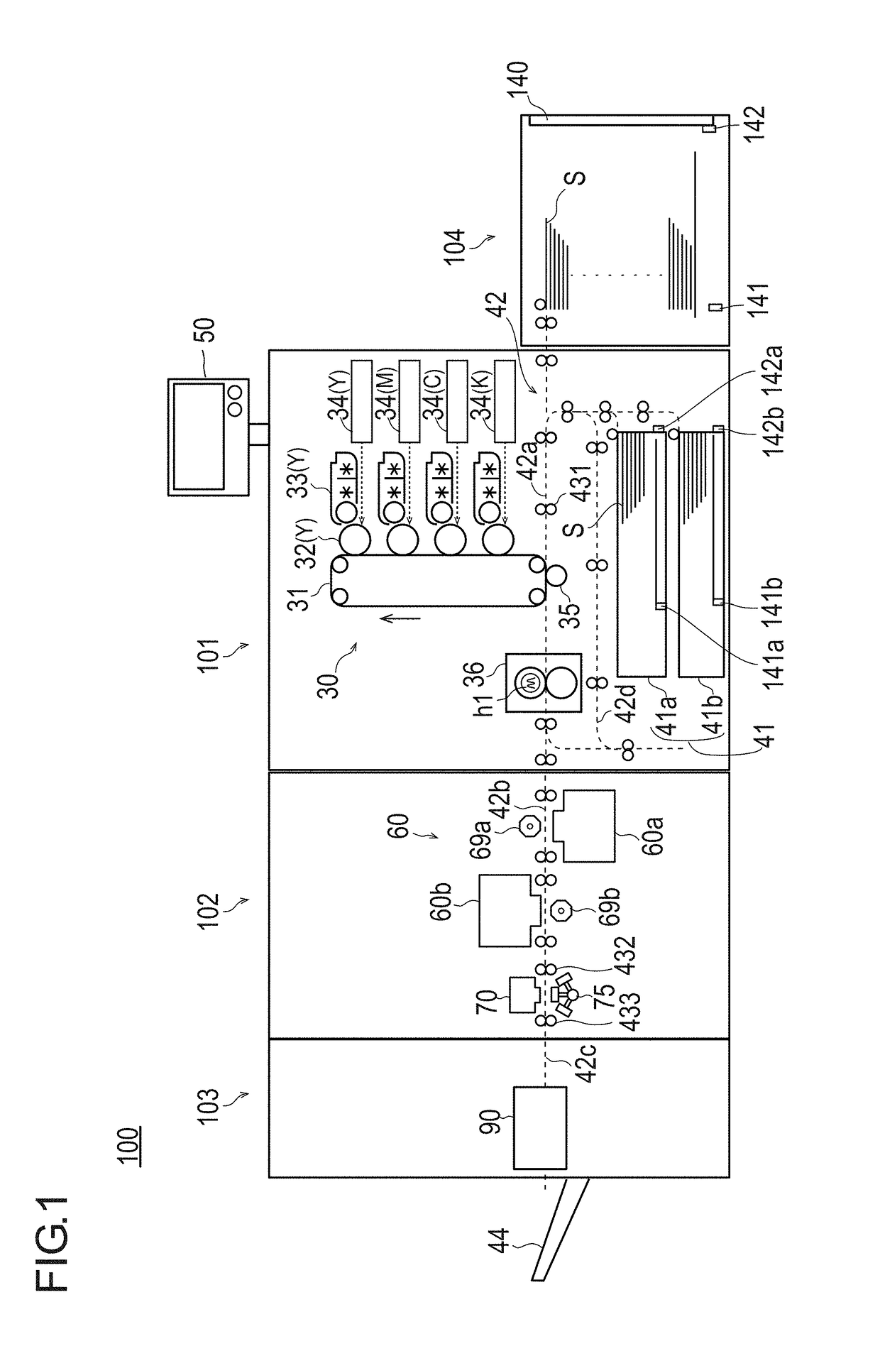
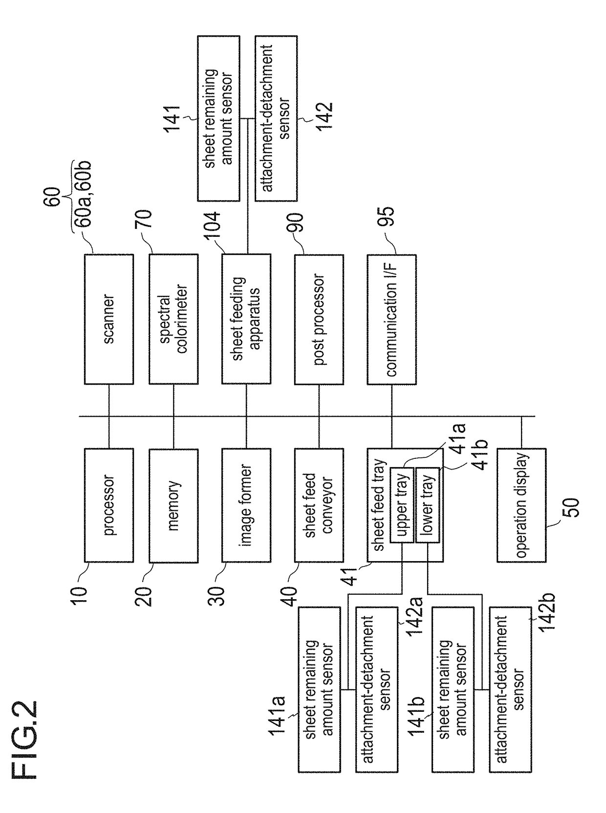
[0024]FIG. 1 is a schematic illustration showing a constitution of an image forming system according to one embodiment of the present invention. FIG. 2 is a block diagram showing a constitution of an image forming system.

[0025]An image forming system 100 includes an image forming apparatus 101, a reading apparatus 102, a post processing apparatus 103, and a sheet feeding apparatus 104. The image forming apparatus 101 performs image formation (printing) for paper sheets (hereafter, merely referred to as sheets). The reading apparatus 102 reads an image on a sheet having been subjected to printing. The post processing apparatus 103 performs post processing for sheets having been subjected to printing. The sheet feeding apparatus 104 serves as a sheet feeder together with sheet feed trays 41, and stores sheets to be fed to an image former 30.

[0026]As shown in FIG. 2, the image forming system 100 includes a processor 10, a memory 20, the image former 30, a sh...

embodiment 2

[0068]The image forming method according to Embodiment 2 is described. Embodiment 2 is only different in processing procedure from Embodiment 1, and since the constitution of the image forming system is the same as Embodiment 1, description for it is omitted.

[0069]FIG. 8 is a flowchart showing the processing procedure for performing automatic adjustment for front and back image positions in Embodiment 2.

[0070]First, the processor 10 determines whether a both side printing job is put in (S21). Here, in the case where the both side printing job is not put in (S11: NO), the processing becomes a standby state. In this connection, in the case where a one side printing job is put in, a usual one side printing will be performed as it is.

[0071]Here, in the case where a both side printing job is put in (S21: YES), the processor 10 checks the sheet feeding apparatus 104 or the sheet feed tray 41 (each of the trays 41a and 41b) to be used for printing of the put-in job (S22). With this checkin...


PUM


Abstract

An image forming method for an image forming system that includes an image former that performs both side printing for one sheet and a sheet feeding apparatus and a tray (sheet feeder) that stores a sheet to be fed to the image former, includes detecting a state change of the sheet feeder; and executing adjustment for a formation position of an image to be subjected to both side printing in a case where a state change of the sheet feeder has been detected.

Description

CROSS-REFERENCE TO RELATED APPLICATION[0001]The entire disclosure of Japanese patent application No. 2017-101902, filed on May 23, 2017, is incorporated herein by reference in its entirety.BACKGROUND1. Technical Field[0002]The present invention relates to an image forming method and an image forming system.2. Description of Related Arts[0003]In recent years, in the printing departments of companies and print shops, color printing by a electrophotographying system called production printing machines has been utilized.[0004]In the production printing machines, quality standards for a positional misalignment of an image is severe. During printing for a certain number of sheets, in the case where a sheet feed tray is changed, or sheets are replenished for the same tray, the position of an image on a sheet becomes different from that on previously-printed sheets, which may not satisfy the quality standards.[0005]Hitherto, in order to prevent occurrence of such a positional misalignment o...

Claims


Application Information

Patent Timeline
Patent Type & Authority Applications(United States)
IPC IPC(8): G03G15/00
CPCG03G15/6567G03G15/5016G03G15/6502G03G15/50G03G15/043G03G15/234G03G15/502
Inventor HIDAKA, HIROKI
Owner KONICA MINOLTA INC
Features
  • Generate Ideas
  • Intellectual Property
  • Life Sciences
  • Materials
  • Tech Scout
  • Unparalleled Data Quality
  • Higher Quality Content
  • 60% Fewer Hallucinations
Learn More