
Composite substrate, method of manufacturing composite substrate, and method of manufacturing flexible board

Active Publication Date: 2018-11-29
MURATA MFG CO LTD
View PDF9 Cites 2 Cited by
  • Summary
  • Abstract
  • Description
  • Claims
  • Application Information

AI Technical Summary

Benefits of technology

This patent provides a way to make composite substrates that can better achieve desired electrical properties and have a higher reliability when connecting a cable to a printed wiring board. The methods for making these substrates are also provided.

Problems solved by technology

As a result, an adverse influence on the electrical characteristics of the cable may be caused.
In addition, depending on the bonding state of the projection-shaped conductor of the fixing portion and the conductor pattern of the cable, an adverse influence may be caused on the reliability of bonding between the cable and the printed wiring board.

Method used


Image

  • Composite substrate, method of manufacturing composite substrate, and method of manufacturing flexible board
  • Composite substrate, method of manufacturing composite substrate, and method of manufacturing flexible board
  • Composite substrate, method of manufacturing composite substrate, and method of manufacturing flexible board

Examples


Embodiment Construction

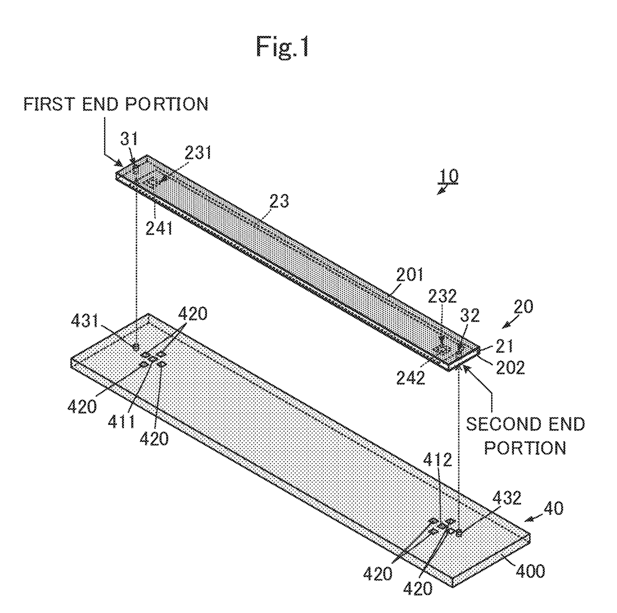
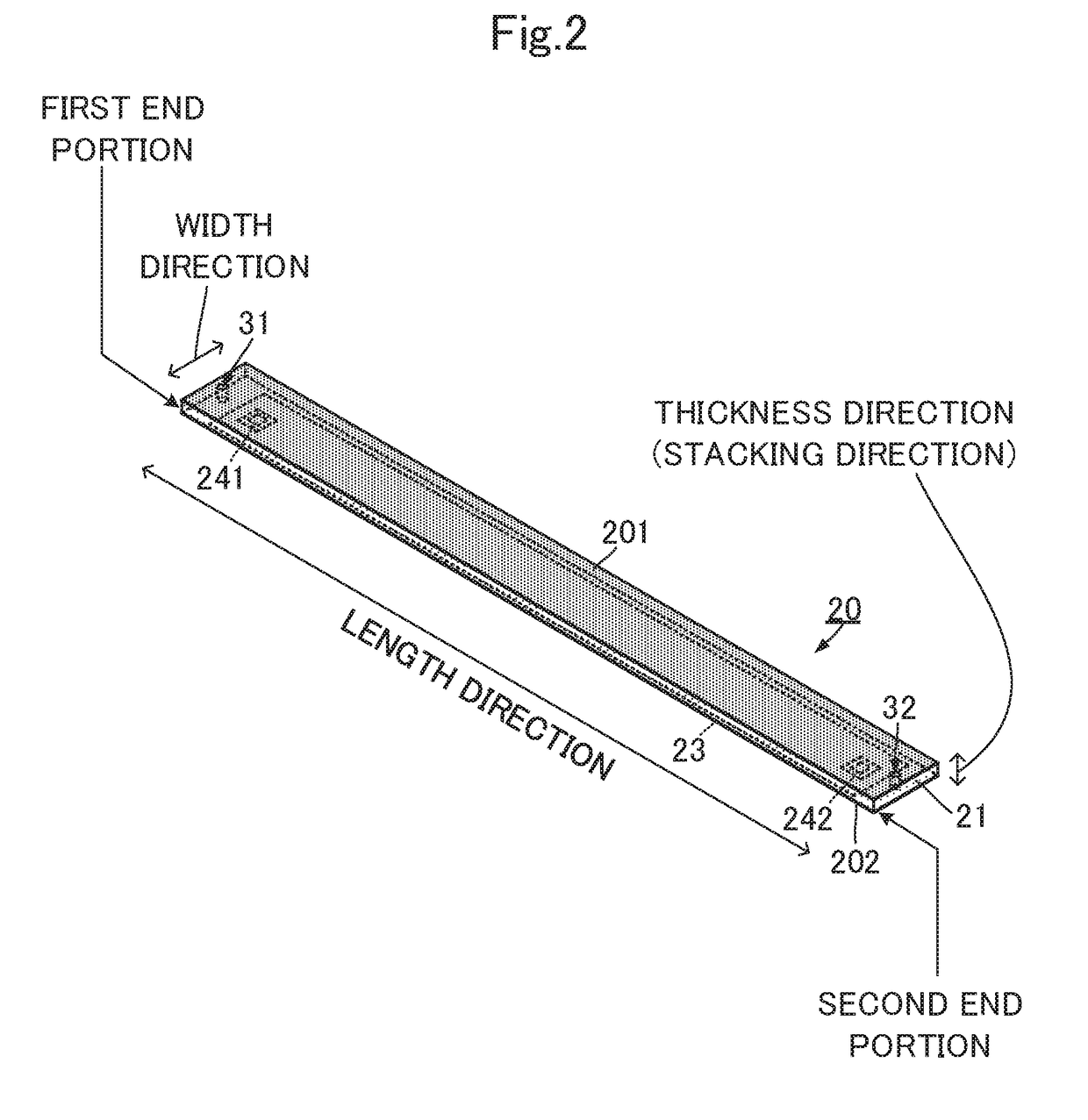
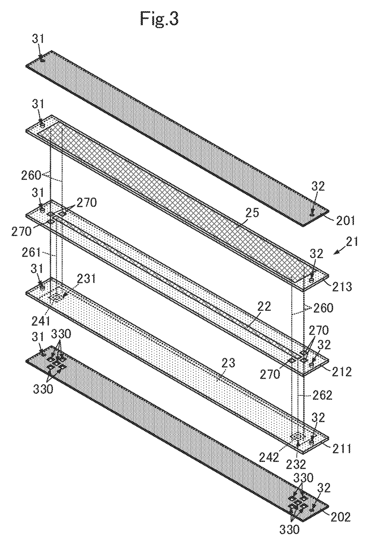
[0058]Composite substrates and methods of manufacturing composite substrates according to preferred embodiments of the present invention will be described with reference to the drawings. FIG. 1 is an exploded perspective view of a composite substrate according to a first preferred embodiment of the present invention. FIG. 2 is an external perspective view of a flat cable as an example of a flexible board according to the first preferred embodiment of the present invention. FIG. 3 is an exploded perspective view of the flat cable according to the first preferred embodiment of the present invention. FIG. 4A is a plan view of the flat cable according to the first preferred embodiment of the present invention, and FIG. 4B is a sectional side view of the flat cable according to the first preferred embodiment of the present invention. FIG. 4B shows a cross section obtained by cutting the flat cable in the middle position in a width direction in FIG. 4A. FIG. 5A is an enlarged sectional si...


PUM


Abstract

A composite substrate includes a flat cable and a mounting board. The flat cable includes a first end portion and a second end portion, and a first bonding portion, a circuit portion, and a second bonding portion in this order in the length direction from the first end portion toward the second end portion. A positioning hole is disposed between the first end portion and the first bonding portion in the length direction. Another positioning hole is disposed between the second end portion and the second bonding portion in the length direction. The mounting board includes a mounting land conductor and a convex portion. The convex portion is fitted in the positioning hole. The mounting land conductor is bonded by surface mounting to an external connection conductor of the first bonding portion and an external connection conductor of the second bonding portion.

Description

CROSS REFERENCE TO RELATED APPLICATIONS[0001]This application claims the benefit of priority to Japanese Patent Application No. 2016-032585 filed on Feb. 24, 2016 and Japanese Patent Application No. 2016-143997 filed on Jul. 22, 2016 and is a Continuation Application of PCT Application No. PCT / JP2017 / 004150 filed on Feb. 6, 2017. The entire contents of each application are hereby incorporated herein by reference.BACKGROUND OF THE INVENTION1. Field of the Invention[0002]The present invention relates to a composite substrate including a mounting board and a flexible board, a method of manufacturing the composite substrate, and a method of manufacturing the flexible board.2. Description of the Related Art[0003]International Publication No. 2014 / 002592 discloses a mechanism in which a cable (a flexible board) is fixed to a printed wiring board. The cable includes a hole. The hole includes a conductor on a wall surface of the hole. The conductor on the wall surface of the hole is connect...

Claims


Application Information

Patent Timeline
IPC IPC(8): H05K1/11H05K1/14H05K3/46
CPCH05K1/118H05K1/14H05K3/46H05K1/144H05K3/361H05K3/368H05K3/4638H05K2201/0367H05K2201/041H05K2203/167
Inventor ITO, SHINGO
Owner MURATA MFG CO LTD
Learn More