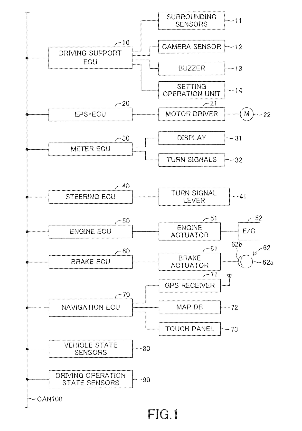
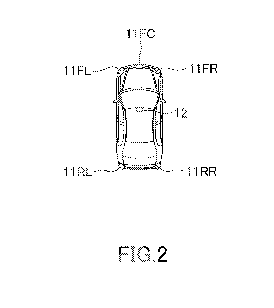
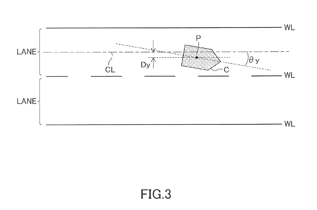
Lane change assist device

a technology of assist device and assist device, which is applied in the direction of vehicle position/course/altitude control, process and machine control, instruments, etc., to achieve the effect of accurate execution

Active Publication Date: 2018-12-06
TOYOTA JIDOSHA KK
View PDF29 Cites 68 Cited by
  • Summary
  • Abstract
  • Description
  • Claims
  • Application Information

AI Technical Summary

Benefits of technology

[0055]On the other hand, the first integral value calculated in one aspect of the present invention does not include the above error caused by the camera sensor (the lane recognition device). Therefore, the first yaw angle return control can be accurately executed so that the yaw angle at the first finish time is the same value or sub

Problems solved by technology

Japanese Patent Application Laid-open No. 2016-126360 does not disclose a mode for controlling the own vehicle by the la

Method used


Image

  • Lane change assist device
  • Lane change assist device
  • Lane change assist device

Examples


first modified embodiment

[0310]Therefore, the original lane return control may be executed according to the flowchart of a first modified embodiment shown in FIG. 16.

[0311]In this case, the driving support ECU 10 calculates the original lane return target trajectory function in Step S81, and executes the steering control based on the original lane return target trajectory function in Step S82.

[0312]Subsequently, in Step S83, the driving support ECU 10 determines whether or not the camera sensor 12 fails to recognize the relative position of the own vehicle in the lane width direction.

[0313]When determining that the camera sensor 12 fails to recognize the relative position in Step S83, the driving support ECU 10 proceeds to Step S84 to calculate the second yaw angle return target trajectory the second target curvature function Cuemergency 2*(t)) in the same manner as Step S68. The second yaw angle return target trajectory is a trajectory for returning the yaw angle to the same value as the yaw angel at the s...

second modified embodiment

[0319]Further, when the camera sensor 12 becomes unable to (fails to) recognize the relative position of the own vehicle in the lane width direction during execution of the original lane return control, the present invention may be executed in the manner of a

[0320]That is, in the above embodiment, when detecting that the lateral position of the own vehicle has reached the original lane return completion target lateral positon (the center position of the original lane), the driving support ECU 10 determines that “an original lane return control end condition is established” in Step S73 of the subroutine B. Therefore, in the above embodiment, when the camera sensor 12 fails to recognize the relative position of the own vehicle in the lane width direction with respect to the lane, the driving support ECU 10 cannot determine whether or not “the original lane return control end condition is established” in Step S73. In other words, when the second interruption condition is established, t...


PUM


Abstract

The first yaw angle return control is started at a first start time when the first interruption condition is established. The actuator is controlled under the first yaw angle return control so that yaw angle at a first finish time becomes a value closer to yaw angle at the lane change start time compared with yaw angle at the first start time. The first finish time comes when a first control execution time passes from the first start time. The actuator is controlled under the second yaw angle return control so that yaw angle at a second finish time becomes a value closer to yaw angle at the lane change start time compared with yaw angle at the second start time. The second finish time comes when a second control execution time longer than the first control execution time passes from the second start time.

Description

BACKGROUND OF THE INVENTION1. Field of the Invention[0001]The present invention relates to a lane change assist device capable of executing a lane change assist control for supporting a steering operation to make a lane change.2. Description of the Related Art[0002]Japanese Patent Application Laid-open No. 2016-126360 discloses a lane change assist device capable of executing lane change assist control that supports a steering operation of a steering wheel when a vehicle makes a lane change.[0003]This lane change assist device can calculate a target trajectory on which a vehicle (hereinafter referred to as “own vehicle”) equipped with a lane change assist device travels when the own vehicle makes a lane change from a lane on which the own vehicle is currently traveling (hereinafter referred to as “original lane”) to a lane adjacent to the original lane (hereinafter referred to as “target lane”). Furthermore, the lane change assist device can control steered angles of steered wheels ...

Claims


Application Information

Patent Timeline
IPC IPC(8): B60W30/095B60W30/18B62D15/02
CPCB60W30/0953B60W30/0956B60W30/18163B62D15/0255B62D15/025G08G1/167G05D1/0214
Inventor FUJII, SHOTA
Owner TOYOTA JIDOSHA KK
Why Eureka
Try Eureka