Conductive structure, lighting fixture, and lighting fixture assembling method

a technology of assembling method and conductive structure, which is applied in the direction of incadescent cooling arrangement, semiconductor devices for light sources, lighting and heating apparatus, etc., can solve the problems of high temperature generation, complex assembling method of lighting fixture, and increase in the cost of lighting fixture production, so as to achieve efficient assembling of lighting fixture and reduce the cost. , the effect of effective removal

Active Publication Date: 2018-12-06
XIAMEN ECO LIGHTING CO LTD
View PDF0 Cites 6 Cited by
  • Summary
  • Abstract
  • Description
  • Claims
  • Application Information

AI Technical Summary

Benefits of technology

[0025]For more detail, in the above-mentioned embodiments, the lighting fixture or the conductive structure thereof can be manufactured without being welted, such that the conventional problems that professional equipment and more complicated process are needed can be solved.
[0026]In addition, the filament closely contacts the heat dissipation device, such that the heat generated by the filament can be effectively removed by the heat dissipation device. Moreover, the lighting fixture assembling method provided by the present invention can more efficiently assemble the lighting fixture. Accordingly, comparing with the conventional techniques, the conductive structure, the lighting fixture and the lighting fixture assembling method have following advantages: low cost, high heat dissipation ability or the efficiency for assembling.

Problems solved by technology

However, such lighting fixture assembling method is complicated and needs an accurate melting technique, or the filament cannot emit light or even falls off.
Besides, if the lighting fixture must be produced via melting, the manufacturer needs expensive equipment and a complicated process, thus the cost for producing a lighting fixture raises.
Additionally, high temperature is generated since the filament generates heat.
Accordingly, the filament may be damaged and the yield for the lighting fixture is accordingly affected.

Method used


Image

  • Conductive structure, lighting fixture, and lighting fixture assembling method
  • Conductive structure, lighting fixture, and lighting fixture assembling method
  • Conductive structure, lighting fixture, and lighting fixture assembling method

Examples


Embodiment Construction

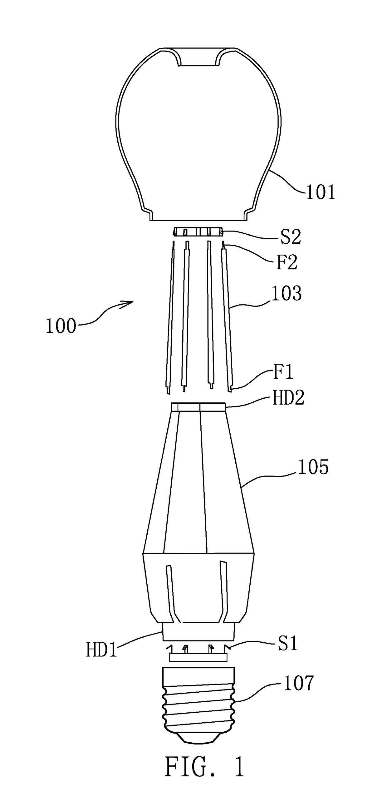
[0035]FIG. 1 is an exploded diagram for a lighting fixture according to one embodiment of the present invention. As illustrated in FIG. 1, the lighting fixture 100 comprises a light bulb 101, a plurality of filaments 103, a first conductive spring sheet S1, a second conductive spring sheet S2, and a heat dissipation device 105. The filament 103 contacts the heat dissipation device 105. In one embodiment, the filament 103 is stripe-shaped and is in close contact with the heat dissipation device 105, but is not limited thereto. Each filament 103 comprises a first filament end F1 and a second filament end F2. The first filament end F1 is connected to the first connection point of the first conductive spring sheet S1 and the second filament end F2 is connected to the corresponding second conductive point of the second conductive string sheet S2. Detail structures will be described below. The heat dissipation device 105 is columnar-shaped in this embodiment and includes a first heat diss...


PUM


Abstract

A conductive structure comprising: a plurality of conductive devices; a first conductive spring sheet, comprising a first connecting point; and a second conductive spring sheet, comprising a second connecting point. Each of the conductive devices comprises a first conductive end and a second conductive end. The second conductive end is connected to the second connecting point, and the first conductive end is connected to the first connecting point corresponding to the second connecting point to which the second conductive end is connected.

Description

BACKGROUND OF THE INVENTION1. Field of the Invention[0001]The present invention relates to a conductive structure, a lighting fixture and a lighting fixture assembling method, and particularly relates to a conductive structure, a lighting fixture and a lighting fixture assembling method which need no melting.2. Description of the Prior Art[0002]Conventionally, a lighting fixture always comprises a filament which is melted to a flexible print circuit (FPC), such that the filament can receive electric power and emits light. However, such lighting fixture assembling method is complicated and needs an accurate melting technique, or the filament cannot emit light or even falls off. Besides, if the lighting fixture must be produced via melting, the manufacturer needs expensive equipment and a complicated process, thus the cost for producing a lighting fixture raises.[0003]Additionally, high temperature is generated since the filament generates heat. Accordingly, the filament may be damage...

Claims


Application Information

Patent Timeline
Patent Type & Authority Applications(United States)
IPC IPC(8): H01K1/16H01K1/58H01K3/06H01K3/16H01K5/00H01K1/42
CPCH01K1/16H01K1/58H01K3/06F21K9/237H01K5/00H01K1/42F21K9/235H01K3/16F21V29/50F21S2/00F21V17/16F21V23/06F21K9/232
Inventor FU, MINGYANCAO, LIANGLIANGSU, LILEILIANG, DIGNWEI
Owner XIAMEN ECO LIGHTING CO LTD
Why Eureka
Try Eureka