Power connector with integrated status monitoring

a technology of power connectors and status monitoring, applied in the direction of power measurement by current/voltage, coupling device connections, instruments, etc., can solve the problems of unbalanced current and voltage phases, limited or predetermined temperature differences during normal operation, and improper coupling, etc., to achieve accurate measurement of power consumption

Active Publication Date: 2018-12-06
HUBBELL INC
View PDF9 Cites 6 Cited by
  • Summary
  • Abstract
  • Description
  • Claims
  • Application Information

AI Technical Summary

Benefits of technology

[0004]Power measurements can be used to monitor the power consumption of the equipment connected through an electrical power connector. In some cases, the ability to accurately measure the power consumption enables an operator to allocate energy costs to various users based on the usage of the equipment.
[0005]Internal and environmental monitoring, in particular temperature, current, and voltage, may be used to identify normal versus abnorma...

Problems solved by technology

When providing power for a data center however, the phases of the current and the voltage may be anticipated to be unbalanced depending on the load on each phase.
If no voltage and/or current is sense...

Method used


Image

  • Power connector with integrated status monitoring
  • Power connector with integrated status monitoring
  • Power connector with integrated status monitoring

Examples


Embodiment Construction

[0017]Before any embodiments of the application are explained in detail, it is to be understood that the application is not limited in its application to the details of construction and the arrangement of components set forth in the following description or illustrated in the following drawings. For ease of description, some or all of the example systems presented herein are illustrated with a single exemplar of each of its component parts. Some examples may not describe or illustrate all components of the systems. Other exemplary embodiments may include more or fewer of each of the illustrated components, may combine some components, or may include additional or alternative components. The application is capable of other embodiments and of being practiced or of being carried out in various ways.

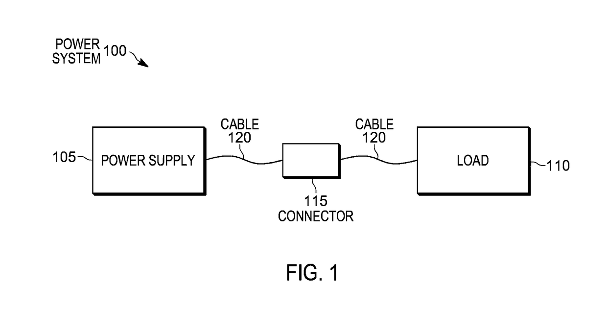
[0018]It should be understood that although the example system described is an electrical connector system, the application may be applied to other systems including electrical connections. ...


PUM


Abstract

An electrical power system including an electrical power connector, a contact configured to electrically connect a power supply to a load, a first sensor configured to sense a first characteristic of the electrical power connector, a second sensor configured to sense a second characteristic of the electrical power connector, and an electronic controller. The electronic controller configured to receive the first and the second characteristics, analyze the first and second characteristics, and determine an abnormal condition based on the analysis.

Description

RELATED APPLICATIONS[0001]This application claims the benefit to U.S. Provisional Patent Application No. 62 / 544,097, filed on Aug. 11, 2017, which claims the benefit to U.S. Provisional Patent Application No. 62 / 512,479, filed on May 30, 2017, the entire contents of both which are incorporated herein by reference.FIELD[0002]Embodiments relate to electrical power connectors.SUMMARY[0003]Electrical power connectors provide a connection between a power supply and a load. Such electrical power connectors may be described in U.S. patent application Ser. No. 15 / 072,672, filed Mar. 17, 2016, which is hereby incorporated by reference.[0004]Power measurements can be used to monitor the power consumption of the equipment connected through an electrical power connector. In some cases, the ability to accurately measure the power consumption enables an operator to allocate energy costs to various users based on the usage of the equipment.[0005]Internal and environmental monitoring, in particular...

Claims


Application Information

Patent Timeline
IPC IPC(8): H01R13/66H01R43/00G01R19/165G01R31/02G01R31/50
CPCH01R13/6683H01R13/6691H01R43/002G01R19/165G01R31/024H01R2103/00H01R24/22G01R1/0416G01R19/2513G01R15/181G01R21/06G01R31/50
Inventor ABUGHAZALEH, SHADI ALEXSAMOJEDEN, MATTHEWPAPAGEORGE, RYANSCANZILLO, THOMASWILLIAMS, MICHAEL
Owner HUBBELL INC
Why Eureka
Try Eureka