Intraocular injection system and methods for controlling such a system

a technology of intraocular injection and control method, which is applied in the field of intraocular injection system and control method, can solve the problems of inability to guarantee the success of the step of disinfecting the accessible portions of the eye globe, the time to incur a risk of microbial contamination of the needle by dust particles, and the inability to increase the concentration and exposure time of iodine indefinitely, so as to achieve less risk of performing

Active Publication Date: 2018-12-20
OPHTHOROBOTICS AG
View PDF6 Cites 2 Cited by
  • Summary
  • Abstract
  • Description
  • Claims
  • Application Information

AI Technical Summary

Benefits of technology

The technical effect of this patent is to create a system and method for injecting into the eye that reduces the chance of causing inflammation afterwards.

Problems solved by technology

The technical problem addressed in this patent relates to improving the process of intraocular injections by reducing the likelihood of damaging the eye during the procedure and minimizing the risk of post-injection complications like inflammation caused by bacterial contamination. Current methods require careful preparation of the eye and significant training for medical professionals, which can lead to errors and discomfort for patients. Additionally, current procedures involve removing a cover without wearing protective equipment, making it easy for bacteria to contaminate the needle. While some automatic injection devices are available, they still require human intervention and come with their own set of challenges and risks.

Method used


Image

  • Intraocular injection system and methods for controlling such a system
  • Intraocular injection system and methods for controlling such a system
  • Intraocular injection system and methods for controlling such a system

Examples


Embodiment Construction

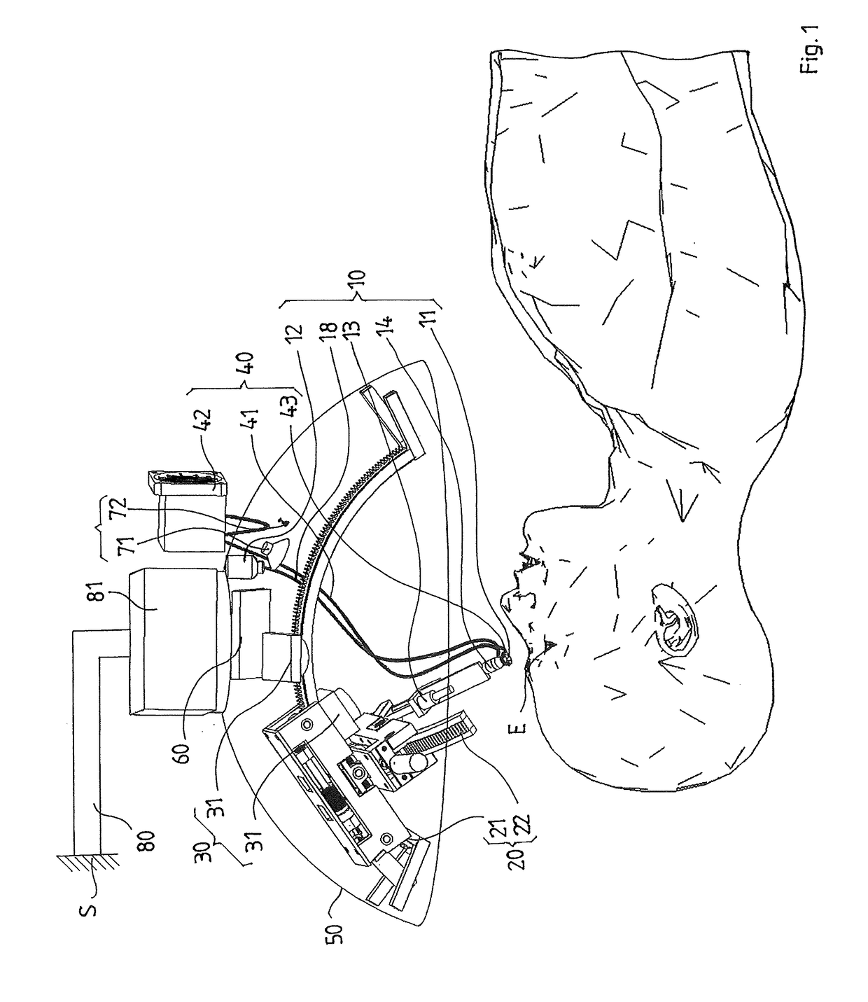
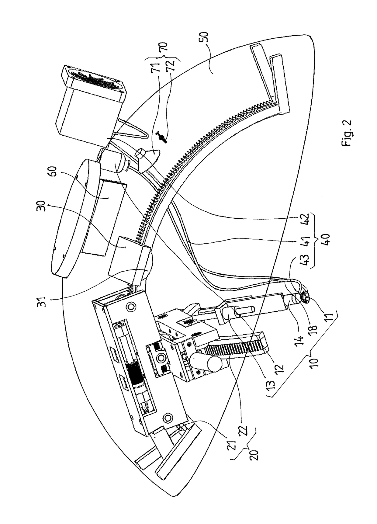
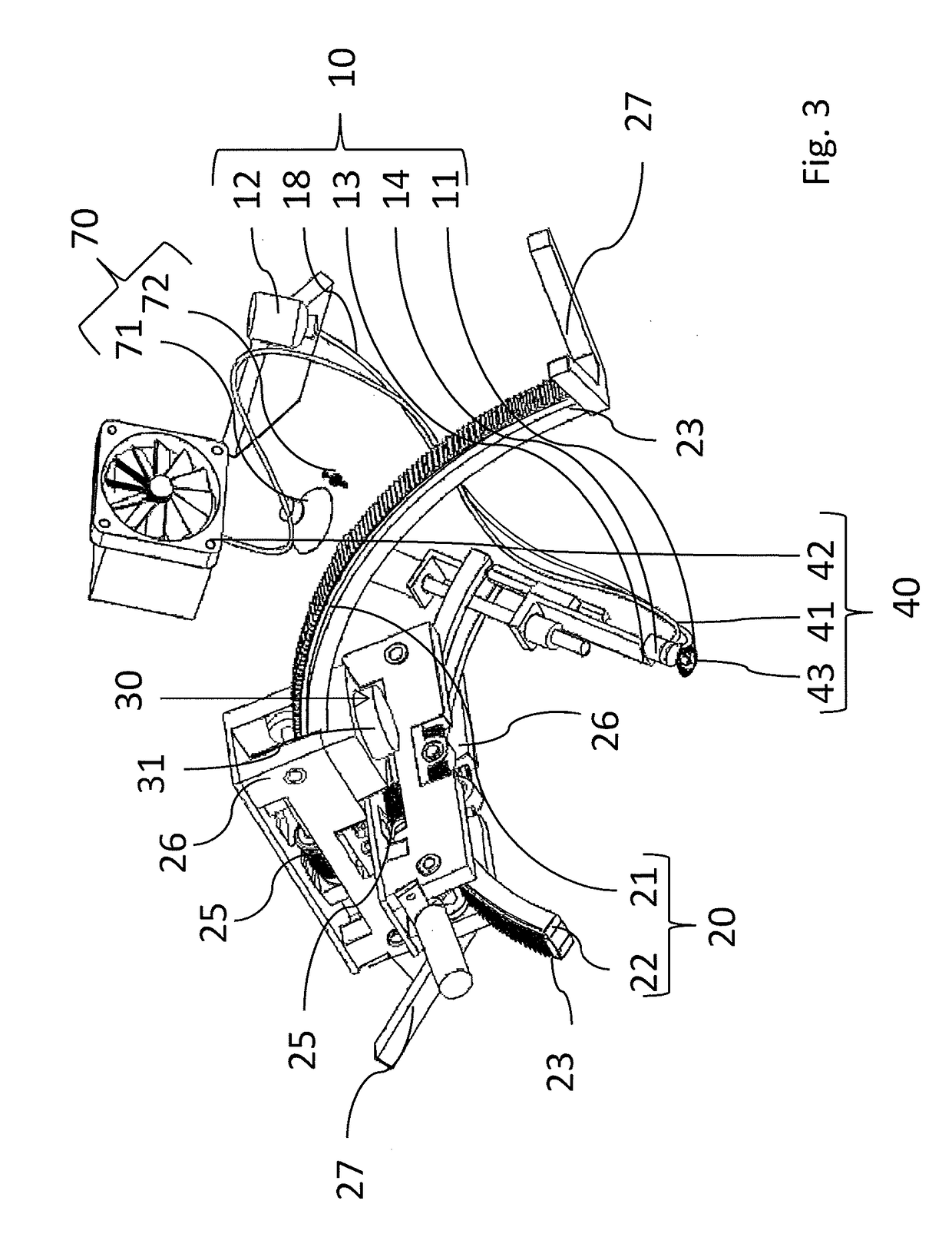
[0056]FIG. 1 shows a schematic side view of an intraocular injection system according to one exemplary embodiment of the invention together with an upper body part of a patient. As basic functional groups, the intraocular injection system comprises the combination of an injection device 10, a robotic manipulator 20, and a detection device 30. All of these functional groups are installed directly or indirectly to the inside surface of a dome-like structure 50 made by an optically transparent material. Thereby, all of these devices can be moved above the head of a patient by moving the dome-like structure 50.

[0057]The injection device 10 comprises a piercing member 11 which can be inserted into an eye globe E of the patient shown following a linear path provided by a spindle-drive motor device 13. The piercing member 11 has the form of a needle and is connected to a syringe body 14. The syringe body 14 is connected to a pump (not shown) and a substance depot 12 via a substance tube 18...


PUM


Abstract

An intraocular injection system for injecting a substance into an eye globe of an animal or human eye, the system comprising an injection device with a piercing member for injection of the substance into the eye globe, the intraocular injection system providing an automated piercing of the eye globe by the piercing member. The system further comprises a robotic manipulator carrying the injection device, the robotic manipulator adapted and configured to move the injection device to a pre-injection position, a detection device adapted and configured to detect a position of a patch placed onto the eye globe and to control the robotic manipulator to move the injection device to the pre-injection position, the pre-injection position being based upon the detected position of the patch on the eye globe.

Description


Claims


Application Information

Patent Timeline
Owner OPHTHOROBOTICS AG
Why Eureka
Try Eureka