Position detecting device

Active Publication Date: 2018-12-20
HONDA MOTOR CO LTD
View PDF2 Cites 0 Cited by
  • Summary
  • Abstract
  • Description
  • Claims
  • Application Information

AI Technical Summary

Benefits of technology

[0017]According to the aspect of (5), when the position detecting device approaches the object detector from the first side in the first direction, the guide section of the lever protrusion comes in contact with the object detector, and the lever member is swung against the second biasing force by an inclination of the guide section. Accordingly, the lever protrusion can avoid the object detector, and the lever protrusion and the position detecting device can be moved to the second side in the first direction. In addition, when the lever protrusion passes beyond a range in which the lever protrusion is in contact with the object detector, the lever member is returned to the state before swinging by the second biasing force, and the lever protrusion is disposed at a position overlapping the object detector. Accordingly, the object detector can be sandwiched between the second abutting section of the lever member and the first abutting section of the holding member. In this way, since the position detecting device can be attached to the object detector by only a simple operation of causing the position detecting device to approach the object detector from the first side in the first direction, an attachment operation of the position detecting device can be easily and rapidly performed without applying a set tact.
[0018]According to the aspect of (6), in the case in which the position detecting device is attached to the object detector from the first side in the first direction, when the lever protrusion rides over the object detector and is disposed at a position which does not overlap the object detector (when in a state in the middle of attachment procedure of the position detecting device), since movement of the pressing member is restricted by the restricting member even the pressing member is pushed toward the second side in the first direction, a worker cannot recognize the movement of the pressing member even when the worker sees the recognition section. Meanwhile, since restriction of movement of the pressing member due to the rest

Problems solved by technology

However, Published Japanese Translation No. 2015-528117 of the PCT International Publication simply discloses that a position detecting device such as the sensor positioning apparat

Method used


Image

  • Position detecting device
  • Position detecting device
  • Position detecting device

Examples


first embodiment

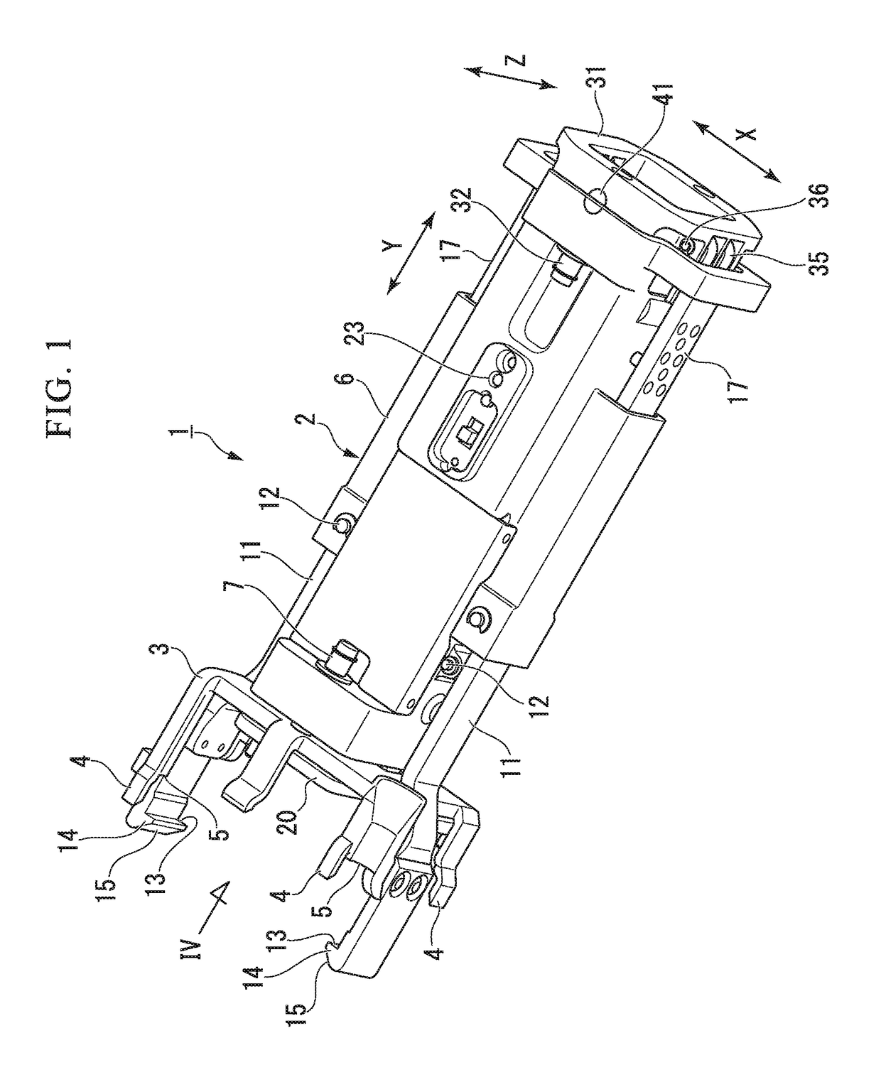
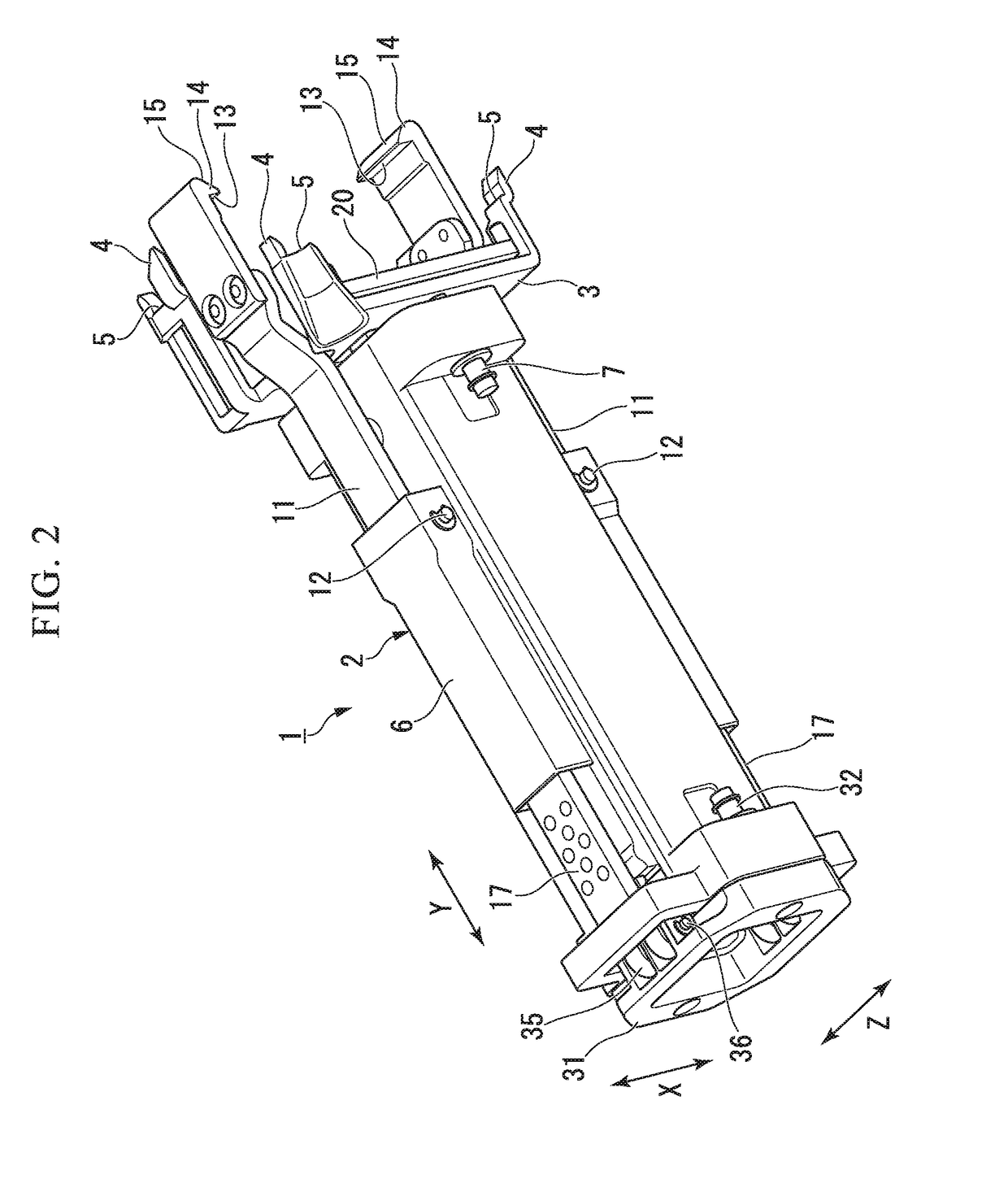
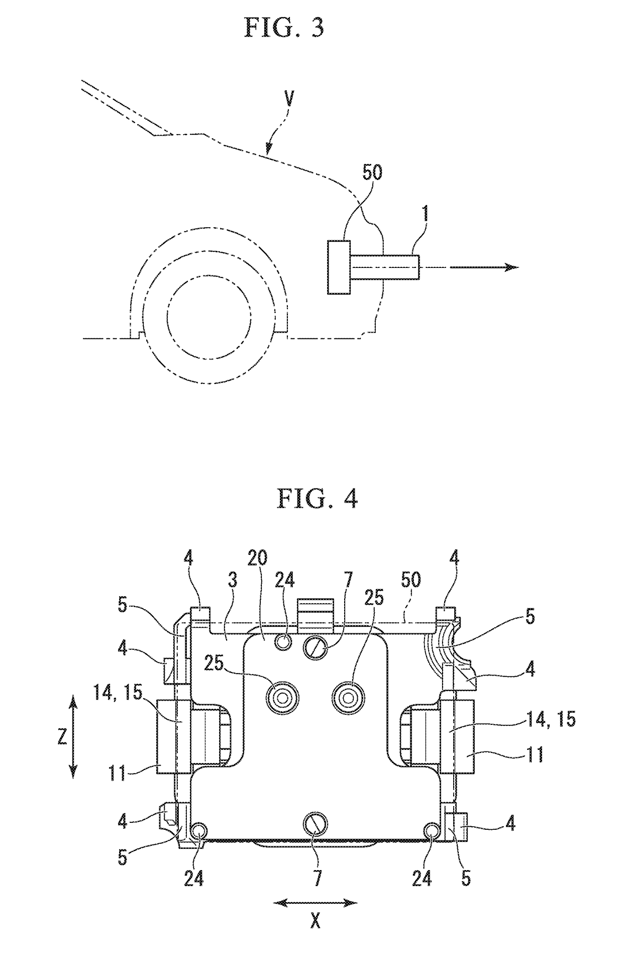
[0044]As shown in FIG. 1 to FIG. 3, a position detecting device 1 is attached to a radar sensor (an object detector) 50 fixed via a bracket or the like at a prescribed position of a vehicle V with a disposition in which a depth direction is oriented in a laser-emitting direction, and used for positional adjustment of the radar sensor 50. The position detecting device 1 is attached with respect to the radar sensor 50 while approaching in the depth direction from one side (hereinafter, referred to as a rear side or a first side) to the other side (hereinafter, referred to as a front side or a second side) in the depth direction. The position detecting device 1 includes a connecting structure 2 fixedly (integrally) connected to the radar sensor 50, and a position reference holder 20 (a position reference member) that is supported by the connecting structure 2 in a state in which a biasing force is applied toward an initial position, that is displaced against the biasing force when the ...

second embodiment

[0101]Next, a second embodiment of the present invention will be described with reference to FIG. 18 to FIG. 21.

[0102]The embodiment is particularly distinguished from the first embodiment in that, while the position detecting device 1 of the first embodiment is a self-contained type including the sensor main body 22 and the display unit 23, a position detecting device 101 is combined with a tester 55 separated from the vehicle V and is configured to perform position detection of a radar sensor 50. In addition, the same components as the embodiment are designated by the same reference numerals and detailed description thereof will be omitted.

[0103]In the position detecting device 101 of the embodiment, instead of the sensor main body 22, a laser pointer 22A (see FIG. 19) configured to irradiate a target board 56 of the tester 55 with laser light, a mirror 22B (see FIG. 20) configured to reflect the laser light emitted from the laser pointer of the tester 55 to the target board 56 of...


PUM


Abstract

A position detecting device used for positional adjustment of a radar sensor serving as an object detector mounted in a vehicle includes a connecting structure connected to the radar sensor, and a position reference holder that is supported by the connecting structure in a state in which a biasing force toward an initial position is applied, that is displaced against the biasing force in a state in which the connecting structure is connected to the radar sensor and that is pushed against a position reference of the radar sensor in a floating support state.

Description

CROSS-REFERENCE TO RELATED APPLICATION[0001]Priority is claimed on Japanese Patent Application No. 2017-119692, filed Jun. 19, 2017, the content of which is incorporated herein by reference.BACKGROUND OF THE INVENTIONField of the Invention[0002]The present invention relates to a position detecting device.Description of Related Art[0003]A vehicle including a radar sensor configured to detect an object such as another vehicle or the like disposed around an own vehicle is known. A radar sensor needs to be accurately aligned so that a system including the sensor is reliably operated. Published Japanese Translation No. 2015-528117 of the PCT International Publication discloses that a sensor positioning apparatus 100 includes a receiver flag 102 and an attachment arm section 104, and the attachment arm section 104 is attached to a radar sensor using a suction pad, an adhesive agent, friction, or the like.SUMMARY[0004]However, Published Japanese Translation No. 2015-528117 of the PCT Inter...

Claims


Application Information

Patent Timeline
IPC IPC(8): G01S7/40G01S7/497G01S13/93G01S13/931
CPCG01S7/4004G01S7/4972G01S13/931G01S13/867G01S2013/9371G01S7/02G01S7/4026G01S2013/93271G01S7/027G01S2013/9327
Inventor OHMOTO, TAKAHIRO
Owner HONDA MOTOR CO LTD
Why Eureka
Try Eureka