Obscuring bus bars in electrochromic glass structures

a technology of electrochromic glass and bus bars, applied in the direction of door/window protective devices, instruments, constructions, etc., can solve the problems that electrochromic windows, especially electrochromic windows, still suffer various problems, and have not begun to realize their full commercial potential

Active Publication Date: 2018-12-20
VIEW INC
View PDF2 Cites 15 Cited by
  • Summary
  • Abstract
  • Description
  • Claims
  • Application Information

AI Technical Summary

Benefits of technology

[0011]Certain embodiments pertain to an electrochromic glass structure comprising a substantially transparent substrate, an electrochromic device disposed on the substantially transparent substrate. The electrochromic device has one or more transparent conductive layers. The electrochromic glass structure further comprises a bus bar configured to power the electrochromic device and an opaque obscuring layer between the one or more transparent conductive layers and the substantially transparent substrate in a region proximal the bus bar. In some cases, the opaque obscuring layer is located in a region between the bus bar and the substantially transparent substrate. In some cases, the opaque obscuring layer has at least a width configured to block view of the bus bar from an observer outside the electrochromic glass structure. In some cases, the bus bar is made of a material with a color and luminescence configured to blend in with background. In one case, the bus bar material comprises one or more of carbon black, graphite, graphite-based materials, graphene, or graphene-based materials.
[0012]Certain embodiments pertain to an IGU comprising a first pane having a first substantially transparent substrate, an electrochromic device disposed on the second substantially transparent substrate, the electrochromic device comprising a first transparent conductive layer proximal the second substantially transparent substrate, an electrochromic stack, and a second transparent conductive layer. The IGU further comprises a second pane having a second substantially transparent substrate, a spacer between the first and second panes, a primary sealant adhering the spacer to the first and second panes, and a pair of bus bars on the first transparent conductive layer, nearest the first pane, and one or more transparent bus bars on the second transparent conductive layer. The pair of bus bars is located between the spacer and the first substantially transparent substrate such that the spacer blocks view of the pair of bus bars from an observer viewing through the second pane. In some cases, the pair of bus bars is made of materials configured to match color and luminescence to the spacer and / or the primary sealant. In some cases, the one or more transparent bus bars are in the viewable region of the IGU. In one case, the additional one or more transparent bus bars are patterned onto the first substantially transparent substrate and then the first transparent conductor layer is fabricated thereon. In one case, the additional one or more transparent bus bars are embedded in the first substantially transparent substrate in at least in the viewable region of the IGU.
[0013]Certain embodiments pertain to an IGU or laminate comprising an electrochromic device on at least one transparent substrate, of at least two transparent substrates of the IGU or laminate and at least one transparent bus bar configured to electrically power the electrochromic device. In some cases, the transparent bus bar comprises a transparent conductive material embedded with conductive particles. In some cases, the conductive particles are nanoparticles. In some cases, the at least one transparent bus bar is a thin layer of metal or metal alloy. In one example, the thin layer of metal or metal alloy is between about 1 nm and about 10 nm thick. In another example, the thin layer of metal or metal alloy is less than about 5 nm thick.
[0014]These and other features are described in more detail below with reference to the associated drawings.

Problems solved by technology

While electrochromism was discovered in the 1960s, electrochromic devices, and particularly electrochromic windows, still unfortunately suffer various problems and have not begun to realize their full commercial potential despite many recent advances in electrochromic technology, apparatus and related methods of making and / or using electrochromic devices.

Method used


Image

  • Obscuring bus bars in electrochromic glass structures
  • Obscuring bus bars in electrochromic glass structures
  • Obscuring bus bars in electrochromic glass structures

Examples


Embodiment Construction

[0034]In the following description, numerous specific details are set forth in order to provide a thorough understanding of the presented embodiments. The disclosed embodiments may be practiced without some or all of these specific details. In other instances, well-known process operations have not been described in detail to not unnecessarily obscure the disclosed embodiments. While the disclosed embodiments will be described in conjunction with the specific embodiments, it will be understood that it is not intended to limit the disclosed embodiments.

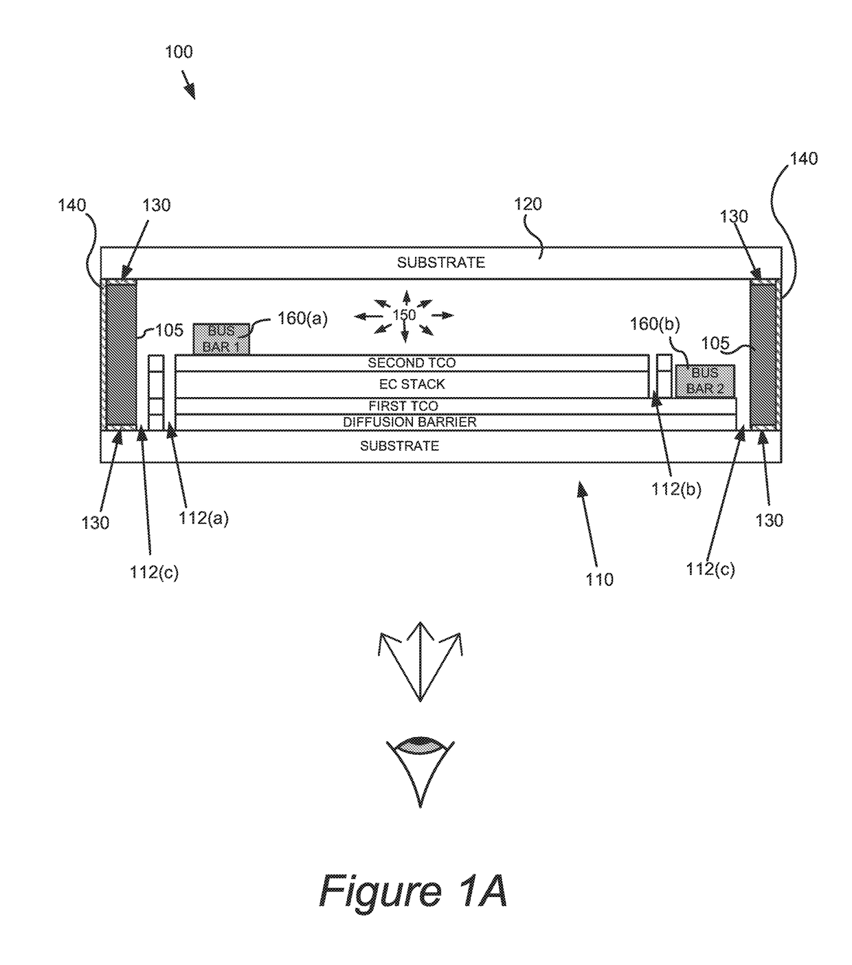
[0035]An electrochromic (EC) glass structure can refer to a structure including one or more EC panes (also referred to herein as EC lites) such as, for example, an insulated glass unit (IGU) or an EC pane laminated to another pane, EC or not. An example of an EC glass structure assembly is an EC window assembly having one or more IGUs. Each IGU is manufactured from two or more panes where at least one of the panes is an EC pane. Each o...


PUM

PropertyMeasurementUnit
widthaaaaaaaaaa
thickaaaaaaaaaa
thickaaaaaaaaaa

Abstract

Embodiments described include bus bars for electrochromic or other optical state changing devices. The bus bars are configured to color match and/or provide minimal optical contrast with their surrounding environment in the optical device. Such bus bars may be transparent bus bars.

Description

CROSS-REFERENCES TO RELATED APPLICATIONS[0001]This application claims benefit of and priority to U.S. Provisional Patent Application 62 / 270,461, titled “OBSCURING BUS BARS IN ELECTROCHROMIC GLASS STRUCTURES” and filed on Dec. 21, 2015. This application is a continuation-in-part of U.S. patent application Ser. No. 15 / 038,727, titled “OBSCURING BUS BARS IN ELECTROCHROMIC GLASS STRUCTURES,” and filed on May 23, 2016, which is a national stage application under 35 U.S.C. § 371 to International PCT Application PCT / US14 / 72362 (designating the United States), filed on Dec. 24, 2014 and titled “OBSCURING BUS BARS IN ELECTROCHROMIC GLASS STRUCTURES,” which claims benefit of and priority to U.S. Provisional Patent Application No. 61 / 920,684, titled “OBSCURING BUS BARS IN ELECTROCHROMIC GLASS STRUCTURES” and filed on Dec. 24, 2013. All of these applications are hereby incorporated by reference in their entirety and for all purposes.FIELD[0002]Certain embodiments disclosed herein relate general...

Claims


Application Information

Patent Timeline
Patent Type & Authority Applications(United States)
IPC IPC(8): G02F1/157G02F1/161G02F1/1345G02F1/01E06B3/67E06B9/24
CPCG02F1/157G02F1/161G02F1/1345G02F1/0147E06B3/6722E06B9/24G02F1/155G02B5/23E06B2009/2464
Inventor ROZBICKI, ROBERT T.JACK, GORDON E.MEHTANI, DISHAFRIEDMAN, ROBIN
Owner VIEW INC
Why Eureka
Try Eureka