
Touch sensor circuit

a multi-touch sensor and touch technology, applied in the field of improved multi-touch sensor and electrostatic pen digitizing system, circuits, can solve the problems of increasing signal loss, not working well on the current solution available, and considering signals, so as to achieve enhanced frequency rejection and enhanced same frequency rejection

Active Publication Date: 2018-12-20
SIGMASENSE LLC
View PDF1 Cites 15 Cited by
  • Summary
  • Abstract
  • Description
  • Claims
  • Application Information

AI Technical Summary

Benefits of technology

The patent text describes a system and method for a digital multi-touch and pen system that works with different types of touchscreens. The system uses special signal patterns to improve the detection and rejection of noise on the touch screen. The technical effect of this system is improved accuracy and reliability in detecting touch on multiple touchscreen types.

Problems solved by technology

The length of time to make a determination increases with the number of electrodes that must be measured, which may affect user experience for relatively large displays that typically have a large number of electrodes to measure, relative to smaller Cap displays used in mobile devices.
These harmonics contain a significant portion of the touch energy change which attenuates faster than the fundamental when passing down a RC impedance chain and back causing considerable signal and increasing signal loss as the touchscreen impedance rise.
The ability to measure a touch in the presence of salt water contamination on the touch sensor is in some cases such as industrial, marine, or military applications, highly desired but does not work well on the current solutions available.
The length of time to make a determination for each mode increases with the number of electrodes that must be measured, which may affect user experience for relatively large displays that typically have a large number of electrodes to measure, relative to smaller Cap displays used in mobile devices.
This system does not allow multi-mode concurrent touchscreen sampling, does not have true simultaneous sampling due to each row using a different bit pattern which effectively scrambles the noise distribution on receipt, is not capable of self capacitance measurements, and due to the use of square wave drive has a receive signal spectrum that contains the primary frequency as well as its harmonics which necessitate lower trace impedance to prevent attenuation of the higher harmonics across the panel.
The systems shown do not allow multi-mode concurrent touchscreen sampling, do not have true simultaneous sampling, use pulse or square wave sampling which does not allows for anti-alias filtering and have high frequency components necessitating lower touchscreen impedances, and all but the last uses mux arrays with high parasitic capacitances.
In other words, the scope of this patent cannot be avoided merely by preparing and making, using, selling, or importing an intellectual property design core that embodies the designs or methods herein.

Method used


Image

  • Touch sensor circuit
  • Touch sensor circuit
  • Touch sensor circuit

Examples


Embodiment Construction

[0087]Novel features believed to be characteristic of the various inventions, together with further advantages thereof, will be better understood from the following description considered in connection with the accompanying drawings in which preferred embodiments of the present invention is illustrated by way of example. It is to be expressly understood, however, that the drawings are for the purpose of illustration and description only and are not intended to define the limits of the invention.

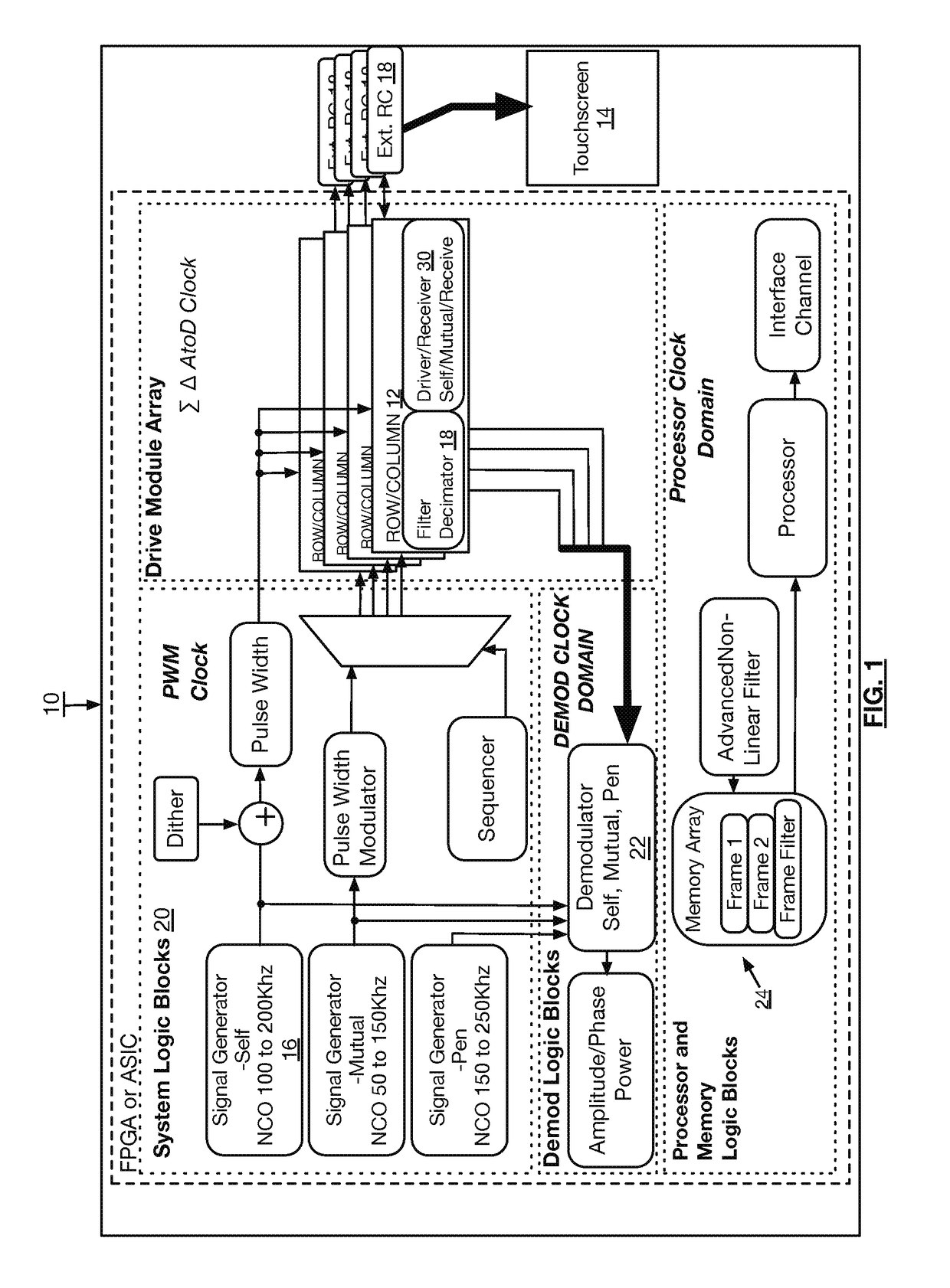
[0088]FIG. 1 is a block diagram of an embodiment of a touchscreen control system including touchscreen drive and receive circuitry 10 constructed with flexible programmable logic embedded in a semiconductor device which may be a touchscreen controller chip, or may be integrated into a larger system on chip arrangement with other system functionality as well. Typically, the circuitry appears in touchscreen or other touch sensor controller circuitry. The circuitry 10 transmits and receives simu...


PUM


Abstract

A touch sensor circuit includes a plurality of drive / receive circuits and a drive signal generation circuit. The drive / receive circuits drive and receive signals from a multi-touch sensor. A drive / receive circuit includes an analog to digital conversion (ADC) circuit and a digital to analog conversion (DAC) circuit. The ADC circuit includes a first input to receive a sensor signal on an electrode of the multi-touch sensor. The sensor signal includes a drive signal component and a receive signal component. The ADC circuit includes a second input to receive an analog reference signal from the drive signal generation circuit. The ADC circuit generates a digital signal based on the analog reference signal and the sensor signal. The DAC circuit converts the digital signal into the drive signal component and the receive signal component is representative of an impedance on the electrode detected and is indicative of a touch proximal to the electrode.

Description

CROSS-REFERENCE TO RELATED APPLICATIONS[0001]The present U.S. Utility patent application claims priority pursuant to 35 U.S.C. § 120 as a continuation of U.S. Utility application Ser. No. 15 / 506,097, entitled “MULTI-TOUCH SENSOR AND ELECTROSTATIC PEN DIGITIZING SYSTEM UTILIZING SIMULTANEOUS FUNCTIONS FOR IMPROVED PERFORMANCE,” filed Feb. 23, 2017, pending, which is a U.S. National Stage Application submitted pursuant to 35 U.S.C. § 371 of Patent Cooperation Treaty Application No. PCT / US2016 / 038497, entitled “MULTI-TOUCH SENSOR AND ELECTROSTATIC PEN DIGITIZING SYSTEM UTILIZING SIMULTANEOUS FUNCTIONS FOR IMPROVED PERFORMANCE,” filed Jun. 21, 2016, which claims priority pursuant to 35 U.S.C. § 119(e) to U.S. Provisional Application No. 62 / 183,062, entitled “MULTI-TOUCH SENSOR AND ELECTROSTATIC PEN DIGITIZING SYSTEM UTILIZING SIMULTANEOUS FUNCTIONS FOR IMPROVED PERFORMANCE,” filed Jun. 22, 2015, all of which are hereby incorporated herein by reference in their entirety and made part of ...

Claims


Application Information

Patent Timeline
Patent Type & Authority Applications(United States)
IPC IPC(8): G06F3/041H03M3/00G06F3/044G06F3/0354
CPCH03M3/458G06F2203/04104G06F3/044G06F3/0416G06F3/03545G06F3/041662G06F3/0446G06F3/04162G06F3/04166
Inventor GRAY, PATRICK TROY
Owner SIGMASENSE LLC
Learn More