Linear motor
a linear motor and motor body technology, applied in the direction of dynamo-electric machines, electrical apparatus, magnetic circuit shapes/forms/construction, etc., can solve the problems of demagnetization of the end of the permanent magnet, difficult maintenance of the spacing between the armature, etc., and achieve the effect of suppressing demagnetization of the permanent magn
- Summary
- Abstract
- Description
- Claims
- Application Information
AI Technical Summary
Benefits of technology
Problems solved by technology
Method used
Image
Examples
second embodiment
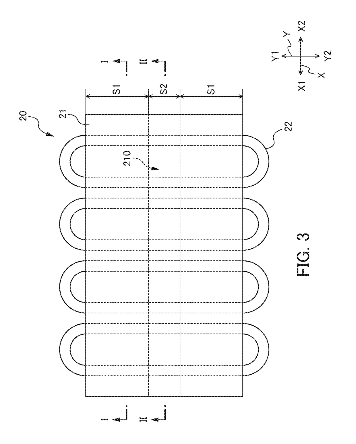
[0045]FIG. 5 is a cross-sectional view of an opening region S2 of an armature 20A of a second embodiment. FIG. 5 corresponds to a cross section of the line II-II in FIG. 3. In the second embodiment, the same reference symbols are attached to portions equivalent to the first embodiment, and otherwise redundant explanations will be omitted.
[0046]As shown in FIG. 5, neither of the main teeth 211 and auxiliary teeth 212 are formed in the opening region S2 of a core 21A of the armature 20A according to the second embodiment, and only the coil 22 is present. It should be noted that, although not illustrated, the configuration of the slot region S1 of the core 21A is the same as the first embodiment (refer to FIG. 4A). In the case of the slot region S1 of the core 21A being configured by the pluralities of main teeth 211 and auxiliary teeth 212 in this way, the opening region S2 may be made a configuration in which neither of the main teeth 211 and auxiliary teeth 212 are formed.
[0047]Also...
third embodiment
[0048]FIG. 6A is a cross-sectional view of a slot region S1 of an armature 20B of a third embodiment. FIG. 6A corresponds to a cross section of the line I-I in FIG. 3. FIG. 6B is a cross-sectional view of an opening region S2 of the armature 20B of the third embodiment. FIG. 6B corresponds to a cross section of the line II-II in FIG. 3.
[0049]As shown in FIG. 6A, only the plurality of main teeth 211 is formed in the slot region S1 of the core 21B of the armature 20B according to the third embodiment, and the auxiliary teeth 212 are not formed. In addition, as shown in FIG. 6B, the main teeth 211 are not formed in the opening region S2 of the core 21B of the armature 20B according to the third embodiment, and only the coil 22 is present. In the case of the slot region S1 of the core 21 being configured only by the main teeth 211 in this way, the opening region S2 may be made a configuration in which the main teeth 211 are not formed.
[0050]Also in the armature 20B of the third embodime...
modified examples
[0052]The first embodiment shows an example in which the same auxiliary teeth 212 as the slot region S1 are formed in the opening region S2, as shown in FIG. 4B; however, it is not to be limited thereto. The formed region and unformed region of auxiliary teeth 212 may be intermingled in the X direction of the core 21. The first embodiment explains an example of the opening region S2 of the armature 20 being provided at the center in the Y direction; however, it is not to be limited thereto. The opening region S2 of the armature 20 may be provided at a plurality of locations in the Y direction.
[0053]The first embodiment explains an example defining the magnet plate 10 as the fixed side and defining the armature 20 as the drive side; however, it is not to be limited thereto. In the linear motor 1, the magnet plate 10 may be defined as the drive side, and the armature 20 may be defined as the fixed side (similarly applies for the second and third embodiments).
PUM
 Abstract
Description
Claims
Application Information
 - R&D Engineer
- R&D Manager
- IP Professional
- Industry Leading Data Capabilities
- Powerful AI technology
- Patent DNA Extraction
Browse by: Latest US Patents, China's latest patents, Technical Efficacy Thesaurus, Application Domain, Technology Topic.
© 2024 PatSnap. All rights reserved.Legal|Privacy policy|Modern Slavery Act Transparency Statement|Sitemap


